Effective MEP clash detection in large-scale projects is important for MEP designers and engineers to mitigate costly rework, timeline delays, and security hazards during construction. Identifying and resolving MEP conflicts in the preconstruction stage leads to seamless construction, better coordination and lower costs.
MEP equipment is crucial for large-scale projects, as it delivers essential services, including heating, ventilation, power distribution, lighting, drainage and water supply. Precise design and integration with other trades like architecture and structure insure greater occupant comfort, improved functionality, and safety.
MEP interference detection flags spatial issues between various disciplines for MEP engineers, fabricators and the on-site team before work begins. This preemptive technique prevents rework, schedule overruns, and potential security issues. This leads to a seamless construction process and faster project delivery.
Unifying multiple models from various trades, including architecture, structure and MEP, in a single virtual 3D model allows a deep assessment of MEP equipment. This digital strategy improves coordination among disciplines for architects, structural engineers, MEP engineers, and project managers, which leads to fewer errors, improved collaboration, and cost-effective construction.
Understanding the basics of MEP clash detection
MEP clash detection includes the identification and resolution of interferences between MEP systems in a construction project. A coordinated and clash-free 3D model mitigates rework and ensures hassle-free installation.
Core principles of MEP clash detection
Clash detection highlights spatial conflicts between MEP equipment, such as a pipe intersecting a duct. Clash resolution in the preconstruction stage ensures smoother workflows, lowers material waste, improves MEP fabrication and leads to a winning project outcome.
Accurate, data-driven, and intelligent MEP integration based on BIM clash detection facilitates streamlined coordination between trades. Minimal ambiguities, improved communication between teams, and an optimized site layout expedite construction speed, lower material waste, and reduce project costs. All of these factors lead to greater efficiency for MEP engineers, fabricators, contractors and owners.
Types of MEP clashes
A coordinated 3D model from various trades can contain various clashes, including hard clashes, soft clashes, and workflow clashes. These three types of clashes are explained below:
Hard clashes: Hard clashes are observed when building members and MEP equipment occupy the same physical space as a structural beam running through a duct. These clashes need to be identified and resolved early on, as they can affect construction and require quick design changes.
Soft clashes: Soft clashes include clearance issues between MEP equipment for code regulations and maintenance access. For example, walls close to pipes can violate building regulations. Resolving soft clashes leads to greater maintainability and prevents costs and rework.
Workflow clashes: Also called 4D clashes, these clashes include scheduling problems between MEP disciplines during actual construction. For example, ductwork installation before fire sprinkler lines can impede user access. Resolving these clashes early on prevents schedule overruns and improves construction sequencing.
Role of MEP clash detection software in large-scale projects
Advanced and feature-driven MEP interference detection tools offer automated clash detection, which provides customized tolerances and clash rules. They also support visual reporting with 3D views and in-depth reports and quick integration with multiple BIM tools. Robust capabilities like 4D clash detection and cloud-based collaboration are important for large-scale projects.
Let us take a quick look at MEP clash detection platforms:
Autodesk Revit: offers basic clash detection features within the design space that are suitable for initial checks.
Autodesk Navisworks: Includes powerful clash detection capabilities with clash reports, simulation and grouping.
BIM360: A cloud-based platform that enables real-time collaboration and clash detection across teams with BIM360 coordinate and its integration with Navisworks.
Avoid costly construction errors with Navisworks clash detection.
Step-by-step guide to performing effective MEP conflict resolution
Before exploring the detailed MEP clash detection process, let’s outline the steps included. This approach provides a comprehensive and systematic interference detection process that leads to effective coordination and winning project results.
1. Preparing the MEP model
Ensure model accuracy, completeness and the use of consistent naming conventions.
Collect and validate MEP design data: Start by collecting updated architectural, structural and MEP models from multiple participants. Ensure these 3D models are created in an IFC or. rvt format to achieve seamless software interoperability within Navisworks or other clash detection software. Validate each 3D model for accuracy, consistency and completeness while considering details like object properties and naming conventions. Also, confirm that every model is consistent with a unit of measurement to prevent ambiguities and ensure precise spatial analysis.
Ensure MEP workflow optimization through standardized file formats: Standardized or interoperable IFC formats improve MEP workflows for architects, engineers and contractors. This reduces information loss and translational problems during export and import, ensuring data integrity for the entire clash detection process. Consistent file formats facilitate team collaboration and access to the most updated data. This seamless approach lowers manual information manipulation and improves overall efficiency.
2. Integrating MEP models into a common platform
Combine models from various trades, including architecture, structure and MEP, in a unified BIM environment.
Discuss using BIM coordination platforms for MEP BIM integration: BIM coordination platforms like BIM360 and Autodesk Construction Cloud play an important role in MEP BIM integration. A unified environment for MEP engineers, contractors and fabricators to store, share and manage 3D BIM models enables real-time communication and collaboration between stakeholders. These platforms make workflows seamless, improve communication and enhance coordination, which leads to faster problem resolution.
Tips for resolving compatibility issues between models: Compatibility problems between 3D models hinder interference detection. To navigate these obstacles, every participant needs to use a standardized format like IFC. Employ a model cleanup process to resolve inconsistencies and problems before importing them into interference detection software. Employ clear communication platforms and rules to foster the quick resolution of compatibility problems.
3. Running clash detection
Use clash detection tools within the software to highlight intersections between various building systems.
How to identify clashes using MEP clash detection software: After importing and aligning 3D models, use the interference detection tool within software like Navisworks. Define tolerance and clash rules based on project needs and industry compliance. Run clash detection tests to highlight clashes. Inspect clash results in 3D views, isolate clashes and assess their severity.
Best practices for generating comprehensive clash reports: Create comprehensive clash reports that include visualizations, including 3D views or screenshots of every clash. Categorize each clash based on severity, type and responsibility. Sort clashes based on their impact on safety and construction to make the complete process seamless for multiple teams. Resolution can also be achieved through the inclusion of element IDs and properties. Ensure reports are easily accessible and shareable with various stakeholders for effective coordination.
4. Analyzing and categorizing clashes
Review clash reports, highlight critical clashes, and assign teams for resolution.
Grouping clashes based on priority (critical, medium, low): Sort detected clashes based on potential impact and severity. Critical clashes like hard clashes would require quick remediation. Medium clashes involve accessibility or code-related problems, while low-priority clashes may be minor, inducing minimal impact.
Importance of collaboration in MEP conflict resolution: Collaboration between multiple project participants like architects, structural engineers, MEP contractors, and construction managers, makes the complete process seamless. Facilitate communication using shared platforms, clash reports and perpetual meetings. Encourage quick dialog and collaborative decision making to realize optimized solutions that satisfy every discipline.
5. Resolving clashes
Collaborate with project participants to redesign, relocate or modify elements to resolve clashes.
Role of MEP coordination meetings in conflict resolution: MEP coordination meetings allow every stakeholder to discuss and provide feedback on clash reports, suggest solutions and resolve conflicts collaboratively. These meetings facilitate clear communication, and ensure every aspect is considered and that design revisions are accomplished.
Updating the MEP design model based on clash resolutions: Once these clashes are resolved in coordination meetings, the MEP model is updated with the said revisions. This step ensures every trade is working with updated data, which prevents further conflicts and fosters a hassle-free construction process.
6. Validating the final model
Rerun interference detection tests to verify that all conflicts are resolved and document the modifications.
Conduct a final review to ensure clash-free MEP systems: Resolve any remaining clashes by conducting an in-depth review of the coordinated 3D model. This includes a visual inspection of the model while rerunning interference detection tests. This strategy verifies that every conflict has been resolved. The final check ensures MEP systems are coordinated and clash-free before actual construction starts.
How MEP design Integration enhances project delivery: Integrated MEP design driven by BIM and clash detection makes the project delivery seamless by enhancing coordination, mitigating errors, and lowering rework. This leads to accelerated construction, reduced costs and higher building quality, which meets functional needs and client expectations.
Implement these proven MEP conflict resolution steps with expert guidance.
Challenges and solutions in BIM MEP clash detection
While MEP interference detection provides significant advantages, it also presents unique obstacles. From the management of complex models and advanced software to efficient collaboration, navigating these problems is critical for successful project handovers. Let’s explore a few challenges and their solutions.
Top 5 challenges in MEP clash detection & coordination
MEP clash detection and coordination are key to ensure streamlined integration of building equipment. Challenges arise from tight spaces and complex geometries. Moreover, misalignment between trades leads to inconsistent 3D BIM models, causing delays and rework.
Inaccurate input data: Errors in input data lead to incorrect interference detection, which causes conflicts that are not identified. Small inaccuracies in dimensions and specifications cause greater coordination problems.
Miscommunication among stakeholders: When project participants are not able to communicate clearly, this results in misaligned needs and overlooked design components. Communication inconsistencies may cause critical modifications to go unchecked.
Limitations of outdated tools: Legacy interference detection tools lack advanced features for managing complex geometries and flag potential clashes. This reduces the efficiency of coordination efforts and extends project schedules.
Lack of standardization: Without a standardized process for data formats and 3D modeling practices, multiple teams struggle to align their work. A lack of standardization leads to the creation of inconsistent 3D models, provoking conflicts and delays.
Delayed design modifications: Late design changes cause clashes that aren’t anticipated earlier. Changes or modifications that are not communicated effectively can impede coordination and cause project delays.
Top 5 solutions for effective MEP model coordination
Effective 3D MEP model coordination depends on advanced and integrated BIM and cloud-based tools for real-time collaboration. Standardized modeling, regular clash detection, and coordination meetings ensure alignment and issue identification across various trades.
Use model validation tools and implement quality control checks: Validating the 3D model ensures MEP systems meet project needs and are error-free. Implementing thorough quality control checks throughout the entire design phase mitigates costly mistakes during on-site construction.
Establish clear communication channels and collaborative platforms: Clear communication platforms ensure every stakeholder is aligned and issues are addressed quickly. Collaborative tools like BIM360 ensure real-time data sharing with updates that improve coordination across various disciplines.
Invest in updated clash detection tools with automated clash grouping: Advanced interference detection is essential for identifying and managing complex clashes between MEP equipment. Automated clash grouping helps organize clashes into manageable sets, allowing teams to resolve multiple issues simultaneously.
Employ 3D modeling practices like LOD, layer standards, and naming conventions: Using LOD standards ensures 3D MEP models are accurate and detailed, providing clarity across multiple trades. Consistence in layer standards and annotations helps simplify model navigation and integration, reducing miscommunication risks.
Deploy strong design management workflows to re-run clash detection tests: Re-running clash detection tests for the entire design process helps with the identification and resolution of issues in the 3D model and ensures its accuracy and validity. This preemptive approach reduces the risk of costly modifications during actual construction.
Success stories on MEP BIM clash detection
The following real-world examples showcase the capabilities of MEP clash detection. From healthcare projects to commercial complexes, preemptive clash resolution reduces costs, saves time, and leads to improvements in project results.
Coordinated and clash-free plumbing model at LOD 300 for a healthcare project in Australia
A design drafting company from Australia outsourced its MEP modeling needs to TrueCADD. 2D plumbing drawings were provided as input. Upon analyzing the input, the team had to navigate challenges, including MEP clash detection and resolution and coordinating architecture and structure with accurate clearances from electrical services. A coordinated and clash-free 3D model at LOD 300 was created using Revit with clash reports in Navisworks.
Upon handing over the deliverables to the client helped them:
Leverage a single solution for 2D, 3D, Details, plumbing and insulation details.
Visualize the drainage systems for underground and upper floors.
Make informed decisions.
Underground Drainage
Upper Floor Drainage
PDF to 3D MEP modeling with clash resolution for a commercial project in the USA
A construction company from the USA approached TrueCADD for a commercial complex project. PDF files of MEP 2D drawings were provided to the team to begin the project. Navigating multiple challenges like missing data within the input, conversion of PDF files into MEP models with international standards and coordinating MEP components led to the creation of a 3D BIM MEP model using Revit. MEP conflict resolution was performed and the files were shared with the client on the Revit CDE.
The final deliverables helped the client:
Leverage improved insights
Save time through clash elimination
Make better decisions for MEP component installation
3D MEP Coordinated Model
PDF to 3D MEP Modeling
Benefits of effective MEP clash detection
Effective MEP clash detection leads to lower rework, mitigates project delays and enhances safety through the listing and resolution of inter-disciplinary conflicts. Here are some benefits of early clash detection.
Streamlined MEP coordination: Remove conflicts and realize a hassle-free MEP installation based on interference detection and collaborative design.
Enhanced project timelines and reduced costs: Identifying clashes in the preconstruction stage reduces reworks and prevents time overruns. This leads to precise schedules, lower material waste and greater project efficiency.
Better communication through MEP BIM integration: Integrating interference detection with BIM improves communication by delivering a shared 3D MEP model for every stakeholder. This fosters a better view, expedites interference resolution and improves collaboration across trades.
Improved design quality: Improve building performance, productivity and sustainability with enhanced MEP systems.
Experience the benefits of precise MEP clash detection in your projects.
Selecting the right MEP clash detection software requires a complete evaluation of parameters like budget, project needs, and tool capabilities. Prioritize features that deliver accurate interference detection, improve collaboration, and make workflows seamless.
Compatibility with BIM tools: Make sure the selected software integrates with existing BIM tools, such as Revit. This helps with direct model import, higher data integrity and smoother workflows.
User-friendly interface and reporting features: Select software with intuitive dashboards and advanced reporting features. This leads to quick navigation, faster clash analysis and communication clarity between users.
Scalability for large projects: Select software or tools that can execute complex models driven by various MEP components and large datasets. Cloud-based tools offer greater scalability and performance for large-scale projects.
Future trends in BIM clash detection and MEP coordination
Looking ahead, let us explore future trends that will shape MEP clash detection and coordination.
Emerging technologies in clash detection and resolution: Artificial intelligence (AI) and machine learning (ML) are being integrated into interference detection tools to automate clash detection, sort clashes based on severity and provide solutions to improve accuracy and efficiency.
The growing role of automation and predictive analytics in BIM-based projects: Automation and predictive analytics are changing BIM-based projects through preemptive clash resolution, improving construction sequencing, and predicting potential issues, which leads to winning project outcomes.
FAQs on MEP conflict resolution
To help you understand MEP clash detection better, a list of FAQs has been compiled.
MEP clash detection identifies and resolves conflicts between MEP equipment in a construction project to mitigate rework and time overruns.
BIM fosters MEP interference resolution through 3D visual representation, which enables preconstruction clash detection and collaborative problem solving.
Yes, various MEP clash detection solutions can be integrated with multiple construction management tools.
Costs vary based on the selected software, project complexities and implementation requirements, but they include software licensing, software upgrades and training.
Conclusion
The future of MEP clash detection will be predictive and intelligent. AI will seamlessly combine with BIM to automatically resolve clashes before they manifest. Expect the creation of smart MEP models that will self-optimize based on real-time clash assessment. This will produce hyper-efficient, large-scale projects with greater safety and sustainable construction workflows.
This shift will allow MEP professionals to focus on optimization and innovation, while ensuring compliance with standards and sustainability goals.
Optimize your large-scale project with effective MEP clash detection.
Microvellum enhances millwork drafting through parametric design, precise detailing, and production integration, improving accuracy and manufacturing support for millwork drafters while reducing errors and streamlining the production workflow.
In millwork drafting, precision and efficiency are crucial factors for success. Millwork drafting in Microvellum offers industry-leading solution that addresses these fundamental requirements through its powerful integration with AutoCAD’s robust engine. This specialized platform offers detailed 3D drawing & modeling tools that help create production-ready output, effectively bridging the gap between design intent and fabrication.
Microvellum’s intelligent parametric objects, ease of creating documentation, and direct manufacturing integration provide substantial benefits for both small custom shops seeking precision and large manufacturing operations requiring consistency and speed across complex projects.
As millwork professionals face increasingly complex designs and tighter production schedules, Microvellum drafting capabilities deliver the accuracy and manufacturing support necessary to maintain quality while meeting demanding timelines.
What is millwork drafting and why it matters
Millwork drafting represents the essential process of creating technical drawings for custom woodwork elements including cabinetry, furniture, architectural details, and decorative components. These drawings serve as the critical communication bridge between designers, engineers, fabricators, and installers, ensuring that all stakeholders work from consistent, accurate information throughout the project lifecycle.
In millwork, even minor errors in measurements or specifications cascade into significant problems such as material waste, production delays, assembly difficulties, and installation challenges. High quality millwork drafting services helps solve these problems with accurately represented components and clear communication of design intent.
This ultimately helps enhance overall project profitability, making effective millwork drafting a critical competitive advantage in the industry. The specialized tools and methodologies within Using Microvellum for custom millwork projects helps address these requirements with accuracy and manufacturing support.
How Microvellum enhances millwork drafting accuracy
The precision achieved through Microvellum drafting process stems from several key technological advantages embedded within the software’s architecture. These capabilities work together to create an integrated drafting environment specifically optimized for millwork applications.
Parametric object-based design
Microvellum utilizes parametric modeling where components exist as intelligent objects with built in rules and relationships. This approach ensures that when one element changes, all connected elements automatically adjust accordingly, maintaining dimensional accuracy and proper relationships throughout the entire design.
For example, when modifying cabinet dimensions, the system automatically updates internal shelving, drawer configurations, hardware placements, and material requirements. This parametric intelligence eliminates the common drafting errors that occur when changes to one component are not accurately reflected in related elements.
This object-based approach also enforces manufacturing rules, preventing designers from creating impossible configurations that would cause problems in production. Each parametric object contains embedded knowledge about manufacturing constraints, material properties, and assembly requirements.
Accurate detailing and specifications
Microvellum shop drawings achieve exceptional detail because the software helps easily manage much of the specification process. Rather than manually drafting each component, the system generates precise construction details based on predefined standards and manufacturing requirements.
The detailing capabilities streamline the creation of critical information including:
Dimensioning that reflects actual manufacturing requirements
Joint details that accurately represent construction methods
Hardware placement that accounts for clearance and structural needs
Finish specifications that properly identify material treatments
This elimination of repetitive manual drafting reduces the potential for human error while ensuring that specifications remain consistent across all project documentation.
Material-specific properties and rules
One of the major Microvellum accuracy benefits comes from its incorporation of material-specific properties and manufacturing constraints directly into the drafting process. The software understands the real-world limitations of different materials and manufacturing methods, automatically applying appropriate rules during the design process.
These material-specific considerations include:
Actual material thicknesses rather than nominal dimensions
Grain direction requirements for aesthetic and structural integrity
Hardware specifications with proper clearances and mounting details
Tooling capabilities and limitations for CNC manufacturing
By embedding these parameters within the drafting environment, Microvellum prevents common errors before they can reach production. The system will flag impossible configurations, inappropriate material applications, or structural weaknesses that might otherwise go undetected until manufacturing.
Comprehensive documentation creation and management
The software’s structured approach to documentation ensures consistent information across all project outputs. From initial shop drawings to final assembly instructions, Microvellum maintains a single source of truth that eliminates discrepancies between different document types.
2D shop drawings created in Microvellum provide clear, detailed information for production that maintains consistency with the 3D model. The comprehensive documentation system includes:
Structured shop drawing production with standardized layouts
Detailed component specifications linked directly to the 3D model
Organized material requirements lists with accurate quantities
Custom reporting capabilities for specific manufacturing needs
Direct output to production systems without manual translation
Simplified revision management that tracks changes across all documents
Consistent documentation standards that maintain quality across projects
The integrated nature of this documentation system offers an advantage over traditional methods where each document type might be created separately. The ability to easily create and annotate 2D plan, elevation, and section drawings ensures comprehensive documentation for manufacturing.
Improve project accuracy with our expert Microvellum millwork drafting.
Microvellum’s integration with manufacturing processes
A defining advantage of millwork drafting in Microvellum is its seamless connection to manufacturing processes. This integration eliminates the disconnect between design and production that often leads to errors, rework, and delays.
Direct CNC machine programming
One of the key Microvellum speed benefits is that it directly generates machine-ready code for CNC equipment, removing the need for manual programming or intermediate translation steps. This direct path from drafting to machining ensures that what appears in the drawings is precisely what gets manufactured.
The software’s CNC integration capabilities include:
Automatic toolpath generation based on component geometry
Tooling selection appropriate for material and operation types
Optimization of cutting sequences for efficiency
Consideration of material hold-down requirements
Validation of machining feasibility before sending to production
By eliminating the manual reprogramming required between design and manufacturing, Microvellum helps remove a major source of errors while reducing preparation time for CNC operations.
Optimized material utilization
Material costs represent a substantial portion of overall project expenses in millwork manufacturing. Microvellum’s cutting optimization features analyze all components in a project and determine the most efficient material yield, creating significant benefits for production operations.
Microvellum optimizes material use in the following ways:
Calculating the most efficient nesting patterns for sheet goods
Considering grain direction and matching requirements
Accounting for saw kerf in material calculations
Optimizing cutting sequences to minimize waste
Maintaining design specifications while improving yield
This optimization reduces waste, lowers material costs, and contributes to more sustainable manufacturing practices all while maintaining design specifications without compromise.
Enhanced communication and collaboration
Microvellum integration helps improve communication between all project stakeholders. The platform’s comprehensive documentation ensures that everyone involved in the project from designers and engineers to fabricators and installers works from the same accurate information.
The collaborative benefits of Microvellum in millwork drafting include:
Consistent information across all phases of the project
Clear communication of design intent to manufacturing
Reduced questions and clarifications during production
Simplified coordination between different departments
Enhanced quality control through shared standards
This improved communication reduces the misunderstandings and information gaps that occur at the handoff points between different project phases, creating a more cohesive process from design through installation
Key features that drive Microvellum’s performance for millwork manufacturers
Microvellum’s specialized capabilities provide millwork manufacturers with a powerful combination of tools and features. These features work together to create an integrated environment that supports the entire manufacturing process.
Comprehensive library system
The extensive component libraries within Microvellum contain thousands of parametric objects specifically designed for millwork applications. These range from basic cabinet boxes to complex architectural elements, all fully customizable while maintaining manufacturing standards.
Millwork professionals leverage this library system to access standard cabinet configurations for efficient design, utilize architectural millwork components for specialized applications. This also helps incorporate hardware-specific objects with proper installation details and maintaindesign consistency across projects through standardization.
For example, a millwork professional can source complex crown molding, reception desk components, wainscoting panels, and built-in wine rack systems from Microvellum’s extensive library all without creating custom elements from scratch.
Powerful customization tools
While the library system provides an excellent foundation, Microvellum drafting tools excel in customization capabilities that allow professionals to modify existing components or create entirely new ones to meet specific design requirements. This flexibility is crucial for custom millwork projects that often include unique elements.
As a custom cabinet design software, Microvellum provides the flexibility needed for both standard and custom projects. The customization capabilities include:
Parametric modification of existing library items
Creation of custom components that maintain parametric intelligence
Development of specialized joinery and construction methods
Design of unique architectural elements for specific applications
For instance, A millwork drafter can select a base cabinet from Microvellum’s library, and adjust dimensions from 30″ to 36″ wide, and all components doors, drawers, and hardware automatically updates while maintaining proper construction standards.
Integrated material management
The software’s material management system allows drafters to specify exact materials, finishes, and edge treatments for each component. This information flows seamlessly from the drafting phase to cut lists and production documentation, ensuring manufacturing accuracy.
Material management features include detailed material libraries with accurate properties, finish and edge treatment specifications with application details, material-specific machining parameters for manufacturing and accurate costing information for estimating and procurement.
For example, when a drafter specifies cherry veneer with PVC edge banding for cabinet doors in Microvellum, this instantly updates all production documents with exact material requirements, machining parameters, and updated cost estimates.
Reduce design time with smart parametric millwork models.
Reducing errors through Microvellum’s systematic approach
One of the most significant Microvellum accuracy benefits is its systematic approach to error reduction throughout the drafting and production process.
Detailed error checking
The software includes built-in validation tools that automatically identify potential issues throughout the design process. These checks happen continuously during drafting, catching errors when they’re easiest to correct rather than discovering problems during manufacturing.
Dimensional validation against manufacturing constraints
Detection of impossible joinery or construction methods
Identification of hardware conflicts or clearance issues
Verification of material applications for appropriateness
Checking of machining operations against tooling capabilities
This proactive approach to error detection prevents costly mistakes from reaching the production floor, reducing rework and material waste.
Version control and revision management
Microvellum provides version control and revision management system that helps tracks changes to components and assemblies. All related documentation are updated automatically while maintaining history of modifications for reference. This ensures that all stakeholders work from current information and simplifies the change order process through systematic tracking.
This systematic approach to revisions eliminates the confusion and errors that occur when changes are implemented manually across multiple document types.
Standardized processes
By establishing standardized drafting and documentation processes within Microvellum, organizations create consistency across projects and between different drafters. This standardization reduces variability and the associated errors that often result from individual approaches to documentation.
Maintains quality standards; improves production efficiency
Specification formats
Standardized documentation for manufacturing
Eliminates confusion; streamlines production setup
Process workflows
Repeatable sequences for common tasks
Increases drafting efficiency; reduces errors
These standardized processes create a systematic approach to millwork drafting that maintains accuracy and quality regardless of project complexity or team composition.
Enhancing custom millwork efficiency with Microvellum
A leading US architectural millwork company required detailed shop drawings for a major commercial project. The client struggled with tight deadlines and needed specialized expertise to handle intricate millwork specifications.
TrueCADD’s team implemented a systematic workflow approach to address these challenges. By utilizing Microvellum’s sophisticated parametric modeling capabilities, our experts developed precise shop drawings and detailed manufacturing documentation. We utilized the software’s seamless AutoCAD integration to enhance production efficiency and generate precise machine-ready outputs.
The final deliverables led to:
Significant reduction in production errors
Optimized material utilization and cost savings
Improved quality assurance throughout manufacturing
Market segments benefiting from Microvellum drafting
Microvellum for millwork offers specialized solutions across various woodworking sectors, with features tailored to different manufacturing requirements. While Microvellum for cabinetry is perhaps its most recognized application, the software serves multiple market segments each with specific requirements and benefits.
Kitchen and bath manufacturers
They leverage Microvellum’s comprehensive library of over 300 pre-built cabinet products to streamline their workflow from concept to completion. The software’s flexibility accommodates both face frame and frameless cabinetry with various joinery methods including screws, dados, cam-locks, and dowels. Extensive hardware options from top suppliers integrate seamlessly with the design, creating an efficient system for kitchen and bath manufacturers.
Closets and home organization manufacturers
Microvellum provides specialized components for walk-in/reach-in closets, pantries, and garage storage solutions. It offers options for both traditional box-style and modern 32mm system construction, with 3D rendering capabilities that enhance client presentations. The software’s integration with third-party design programs further streamlines the process for closet specialists.
Office furniture manufacturers
They utilize the versatile office furniture expansion in Microvellum’s foundation library. The parametric models allow for custom sizes, shapes, and hardware options while maintaining manufacturing standards. The software’s seamless data management from design to production adapts to varying construction methods and hardware requirements common in office furniture manufacturing.
Custom millwork products
Custom millwork operations leverage Microvellum’s flexibility for creating reception areas, bars, die walls, and store fixtures. The advanced parametric engineering tools accelerate the custom product creation process up to 70% faster than traditional methods. Source:microvellum.com
The software’s 3D model analysis capabilities ensure that even the most complex custom designs are CNC ready for manufacturing.
Conclusion
Millwork drafting in Microvellum offers a powerful combination of parametric modeling, automated documentation, and direct manufacturing integration that creates a comprehensive solution for millwork drafting.
Microvellum’s returns in terms of error reduction, manufacturing efficiency, and production precision justify the adoption for serious millwork operations facing increasingly complex projects and demanding timelines.
As the industry shifts toward more customized products, the advantages offered by millwork drafting services using Microvellum will become increasingly valuable. The platform’s ability to maintain precision while streamlining the connection between design and manufacturing positions it as an essential tool for millwork professionals committed to excellence in the growing market.
Ensure design accuracy with our parametric drafting approach.
Using Revit for precast concrete modeling and precast shop drawings improves project efficiency and coordination and reduces errors. Clear BIM-based visualization and communication lead to quicker approvals, fewer reworks and successful project handovers.
Precast concrete offers significant advantages over on-site casting, including improved quality control and faster schedules. However, the complexity of precast design and coordination demands robust tools. Revit, with its BIM capabilities, provides one of the best precast concrete modeling and detailing solutions.
Revit enables the creation of precise 3D models of precast elements like slabs, walls, and connections. Concrete modeling in Revit facilitates accurate design, promotes clash detection, and automates the creation of precast shop drawings with detailed dimensions, views, and schedules. Integrating structural analysis and fabrication machinery streamlines the entire precast workflow.
Efficient workflows in precast concrete detailing are important to expedite project schedules. Streamlined processes lower errors, improve coordination between design and production teams and enhance resource utilization. This article explores how Revit enhances communication between design and fabrication teams, leading to efficient production processes and reduced errors.
The precast concrete market is projected to grow from USD 150.2 billion in 2025 to USD 247.5 billion by 2035, driven by its durability, cost-effectiveness, and ease of installation in construction. Key segments, including walls, floors & roofs, and structural beams, hold the largest market share due to high demand across residential, commercial, and industrial sectors.
Precast Revit modeling enables accurate 3D representation of precast members through specialized families and tools. The process seamlessly integrates reinforcement details, connection specifications, and production data. This integrated approach supports efficient fabrication and streamlines installation workflows.
Basics of Precast Concrete for Designers and Engineers
Precast concrete refers to concrete members that are manufactured in a controlled setting before being sent on-site for assembly. It ensures high quality, expedited construction timelines, and lower labor costs. Its significance lies in its capability to enhance project sustainability, efficiency, and structural integrity in present-day construction workflows. It also helps precast manufacturers with the flexibility to create complex shapes and customized finishes.
Using the capabilities of precast-driven software in Revit unlocks greater precision and efficiency for precast concrete projects. These tailored tools transform modeling, detailing, and documentation by offering various advantages over traditional techniques. Here are the top three benefits with their impact.
Improved quality control: Precast concrete is built in an off-site and controlled factory setting, which ensures consistent quality, accurate mix proportions, and lower defects. It mitigates variations found with on-site casting. Thorough testing and inspections improve durability, strength, and performance, which leads to greater reliability in construction projects.
Reduced construction time: Since precast members are created off-site and cured before handover, installation at the site is accelerated. This removes delays produced by changing weather conditions and lowers on-site labor needs. Quick assembly leads to planned project timelines, which makes it ideal for commercial development and large-scale infrastructure.
Enhanced durability: Precast concrete is resistant to harsh environmental settings, which includes chemicals, weather, and fire. Its dense composition reduces water absorption, lowers cracks, and mitigates structural damage. This results in long-lasting construction with lower maintenance costs.
How precast modeling simplifies design processes for precast designers, structural engineers, architects, and concrete manufacturers
Precast modeling makes the design process seamless by supporting precast designers, structural engineers, architects, and concrete manufacturers to collaborate effectively. Using digital tools like Revit, it improves accuracy, enhances component visualization, optimizes layouts, and lowers errors. This ensures faster and cost-effective production and streamlined integration into construction projects.
Precast modeling also provides real-time adjustments and updates by helping stakeholders monitor modifications simultaneously. This dynamic workflow lowers delays driven by miscommunication and makes sure every team works with current design. Moreover, it also supports effective material planning, lower waste and costs while improving the performance and quality of the final project.
Revit’s Capabilities for Precast Modeling
Expediting precast concrete modeling in Revit includes utilizing the capabilities of specialized tools. Dynamo, a visual programming tool, enables complete automation of repetitive tasks, including the creation of complex geometries, reinforcement placing, and connection creation. Plugins, including the Structural Precast Extension for Revit, deliver dedicated tools to model custom precast elements, manage connections, and generate shop drawings.
Key functionalities in precast 3D modeling include segmentation for effective precast handling, accurate reinforcement placement for structural integrity, and streamlined connection integration for precise assembly.
Segmentation: Segmentation breaks down large precast members into smaller, manageable pieces, which makes it easier for transport and on-site assembly. This helps enhance logistics and lower handling costs while preserving the integrity of the complete structure. Dividing elements strategically helps precast members align together during the construction process.
Reinforcement placement: It ensures accurate positioning of reinforcement within concrete which optimizes the structural strength of every precast element. Reinforcement modeling prevents the creation of weak points, which ensures structural stability and durability. This level of accuracy is critical to achieve high safety standards and ensure every precast member performs as intended under various load conditions.
Integration of connections: It is required for accurate and effective precast design and assembly. Modeling accurate alignment and connection details, engineers and precast manufacturers ensure accurate fitment, while reducing the requirements for costly modifications and overall enhancements in coordination.
Using the capabilities of precast-driven software in Revit unlocks greater precision and efficiency for precast concrete projects. These tailored tools transform modeling, detailing, and documentation by offering various advantages over traditional techniques. Here are the top five capabilities with their impact.
Leverage our Revit expertise for accurate precast shop drawings and modeling.
Rapid creation of complex precast members with predefined parameters.
Reduction in manual modeling time.
Parametric design
Modification of dimensions and configurations through parametric controls.
Design flexibility and efficient iterations.
Connection design and detailing
Simplification of the creation and documentation of complex connections.
Accurate representations and clash detection.
Automated shop drawings
Extraction of in-depth precast shop drawings with detailed dimensions, views, and annotations.
Minimization of manual drafting and errors.
Improved collaboration
Leveraging coordination and communication using a unified Revit model.
Streamlined workflows, mitigated errors, and faster approvals.
Revit improves collaboration between architects, structural engineers and manufacturers. By centralizing project data within a single model, Revit streamlines workflows, mitigates errors, and enhances coordination. Designers can generate accurate and detailed precast elements, while engineers can analyze structural integrity. Manufacturers can extract precise and detailed shop drawings for precast concrete design in Revit from a shared platform, which facilitates efficiency for the entire project lifecycle.
Setting Up Your Revit Environment for Precast Modeling
Setting up a Revit environment for precast modeling requires loading families, configuring project tolerances and units, and generating view templates with settings for precast elements. Using predefined settings and templates ensures consistency and makes the modeling process seamless.
Template and Family Setup for Precast Modeling
The creation of standardized families and templates is crucial for precast modeling workflows with tools like Revit. These templates ensure higher consistency for the entire project, which reduces issues and accelerates the 3D modeling process. Predefined families, settings, and views tailored for precast concrete streamline design, documentation, and fabrication. Using these customized families, designers and engineers can create precise precast models, which ensure every component aligns with planned project parameters.
Follow these key steps
Setup a Revit template: Build a bespoke Revit template to streamline project initiation.
Add views, schedules, and sheets: Predefined setup reduces manual work and expedites delivery.
Load precast families: Establish connections, slabs, walls, and embeds for faster model creation.
Parameterize all the families: Add parameters to filter, sort, and schedule members efficiently.
Set size and materials: Configure families with accurate dimensions, material type, and reinforcement detail.
Facilitate fast tracking and coordination: Employ naming consistency and tags to support seamless team collaboration.
This methodology ensures an error-free workflow to make the design and fabrication process seamless.
Project Parameters and Shared Parameters for Precast Design
Setting up projects and shared parameters is critical for effective management and tracking of precast members in concrete modeling. Project parameters are used to define required properties, which are specific to the entire project including dimensions, material types, and load-bearing capacities. Shared parameters allow the creation and use of consistent data between various families and components within the 3D precast model.
Setting these parameters, designers can ensure every precast member complies with the exact specifications to improve coordination and mitigate errors. These parameters facilitate precast element tracking by linking comprehensive information on schedules, which enables real-time updates and quick progress monitoring, improved material use, and faster fabrication timelines.
Shared and project parameters work in sync to simplify precast design and coordination.
Define project parameters: Standardize every precast component data with key values.
Setup shared parameters: Utilize parameters to achieve consistency across required model components.
Assign various values: Apply dimensions, material types, and reinforcement to every component.
Tag elements for filtering: Integrate tags to group, find, and manage components.
Auto-populate schedules: Use parameters to automate schedules and lower manual work.
Enable parameter-driven filters: Employ filters to visualize and organize required model components.
Facilitate coordination: Authorize teams to extract valuable data for accurate quantity takeoffs.
Expedite documentation: Streamline drawings and model tracking by applying parameters.
Manage precast members: Monitor, update, and review every precast member in the 3D model.
Efficient Concrete Modeling Techniques for Precast Elements
Effective concrete modeling techniques include utilizing tools to create accurate and in-depth representations of concrete members. This involves the use of capabilities to generate complex shapes, manage data with parameters and generate schedules for seamless documentation.
Creating Precast Walls and Slabs
Here is a step-by-step guide to modeling precast walls and slabs in Revit.
Inserting Connections and Reinforcements
To accurately represent precast connections, use Revit families for connection types like bolts, welds, and plates. For reinforcement, utilize the “Rebar Tool” to include Rebar within precast elements, which defines size, spacing, and lapping for structural drawings. This ensures structural drawings reflect accurate reinforcement configurations, supporting efficient production, and assembly of precast elements while managing compliance with industry standards and design specifications.
Utilizing Revit Add-Ons for Precast Design
The Autodesk Precast Extension in Revit is a tool for making concrete workflows seamless. These tools simplify the creation of precast elements like slabs, walls, and connections, by delivering specialized tools for modeling, segmentation, and reinforcement. The extension is also used to automate shop-drawing creation like sections, views, and schedules, which improves productivity and reduces errors in precast construction.
The Autodesk Precast Extension for Revit enhances design and modeling of precast elements including slabs, walls, and connections. It delivers advanced tools for element segmentation, automated generation of shop drawings, and reinforcement detailing, ensuring greater model efficiency, reinforcement accuracy, and seamless documentation workflows.
Generating Accurate Precast Shop Drawings in Revit
Creating accurate precast shop drawings in Revit requires the use of a dedicated view template and filters to split precast members. Accurate dimensions, annotations and schedules provide detailed information on fabrication and installation workflows.
Automating Shop Drawing Creation
Engineers can significantly speed up their shop drawing documentation process in Revit through built-in automation tools and extensions like Autodesk Precast. The customization of predefined views and sheets specifically for shop drawing needs serves as the foundation for streamlined workflows. From there, automated capabilities efficiently extract plans, sections, elevations, and details – complete with precise dimensions and annotations.
Annotating and Detailing Drawings
Best practices to add annotations and details in Revit include standardizing symbols, clear dimensioning, and consistent labeling. Ensure that every annotation is precise and positioned to prevent clutter. Use predefined annotation families, maintain drawing scale accuracy, and check for compliance with standards and local codes to improve clarity and mitigate errors.
Utilize standardized annotations: Ensure consistency in fonts, text size, and line weights for notes, dimensions, and symbols throughout the project.
Comply with industry standards: Follow regional or project-specific standards like AIA, ISO, etc. which adhere with regulatory guidelines.
Add relevant data: Add reinforcement information, material specs, and connection types to annotations and details.
Use callout details: Highlight important areas that need urgent attention, which ensures they are placed in a clear view.
Be concise: Avoid cluttering annotations with unnecessary information to maintain reading clarity for fabricators and contractors.
Maintain consistency: Regularly check annotations to match the 3D model to prevent ambiguities between design and execution.
Use Revit families and tags: Utilize pre-configured families and tags, or customize them to build precast members, which ensures effective visualization of required details.
Check clarity: Ensure every annotation is clear and understandable to every project participant to avoid misinterpretation during construction.
Quality Control and Review Processes
Implementing quality checks to include precision and consistency in shop drawings is crucial for successful project outcomes. Consistently viewing and cross-referencing shop drawings with the planned design ensures every detail including dimensions, materials, and reinforcement is accurate. The use of automated tools in Revit flags issues and helps with performance checks for complex precast elements. Collaborating with designers, structural engineers, contractors, and fabricators during the review stage helps with preemptive issue identification.
Establishing structured approvals where various stakeholders sign off on every stage guarantees every shop drawing aligns with project parameters and adheres to industry standards. Quality control for precast concrete drawings centers on thorough review processes. The review can incorporate interference detection while ensuring compliance with ACI and PCI industry standards. Detailed verification of dimensions, connections, and reinforcement specifications can enhance drawing accuracy and reliability.
Case Study: Streamlining Precast Modeling with Revit
A 3D precast model in Revit with 5 mm clash coordination leads to time and cost savings.
A precast manufacturer from the UAE outsourced its need to create a precast model at LOD 450 for a residential project in the UAE. CAD drawings, PDF, and Excel files were provided as input. Using Revit and Navisworks, the team at TrueCADD used concrete modeling workflows to create a 3D model at LOD 450, with precast shop drawings and Bar Bending Schedules (BBS). The final model handed over to the client led to:
Clash coordination of the model under 5 mm for M60 concrete grade
Quick deliverable TAT with 100% accuracy
Time and cost savings
A unique ID integrated with each structural element for precise planning, sequencing, and erection
Building Perspective View
Building Image
Building Internal View
Staircase Reinforment
A Revit structural model at LOD 450 saves costs for an office-building project in India.
A leading precast manufacturing firm from India outsourced its rebar modeling needs to TrueCADD for an office-building project. The firm provided 2D drawings and structural design of rebar and concrete, and the team navigated coordination challenges to create a clash-free structural model at LOD 450 in Revit and Navisworks with Bar Bending Schedules. Handing over the final deliverables to the client led to the following:
A full sheet setup with accurate documentation
Cost savings with accurate and efficient deliverables and results
Corbel Details and BBS
Revit Structural Model
Shop Drawings
Structural Shop Drawings
Tips and Best Practices for Accelerating Precast Workflows
Project teams can establish a more efficient concrete modeling workflow through early collaboration in preconstruction. Using Revit and specialized plugins enables precise model creation for contractors. The workflow naturally progresses to automated shop drawing generation, complete with detailed annotations and schedules. This integrated approach reduces errors while accelerating project delivery timelines.
Collaborative Workflows for Precast Modeling
Setting collaborative workflows for precast modeling
Establishing collaborative workflows for precast modeling includes deploying clear communication protocols. Utilize Revit’s work-sharing capabilities and conduct perpetual model reviews. Standardized and collaborative modeling practices promote a team culture that is effective for precast modeling and shop drawing creation.
Making efficient use of cloud-based platforms like BIM360 and shared models
BIM360 fosters seamless communication and coordination using real-time model access, communication platforms, and thorough change management. Clarity in roles and responsibilities for 3D model management ensures consistency and data integrity.
Understanding the significance of role-specific permissions and clash detection
Role-based permissions in cloud-based collaboration platforms like BIM360 prevent unauthorized changes. Clash detection flags and resolves conflicts to streamline precast design and improve overall project coordination.
Leveraging BIM Standards for Precast Design and Concrete Shop Drawings
Adhering to BIM standards like AIA or ISO 19650 protocols
Integrating BIM standards including AIA protocols or ISO 19650 in the precast model enhances precast workflow interoperability and efficiency. Standardized information exchange and naming conventions streamline collaboration and mitigate errors across various project lifecycles.
Standardized workflows and consistent modeling
The use of standardized workflows and consistent modeling techniques improves precast model quality and ensures the creation of precise precast shop drawings. Clarity in guidelines reduces errors and rework, which leads to efficient 3D model creation for precast members.
Advantages of integrating BIM standards
Integrating project-specific and national standards lowers errors and ensures complete project compliance. Consistent data and processes enhance communication, interference detection, and project coordination to reduce risks and enhance efficiency.
Explore How BIM Transforms Prefab & Precast Construction.
Revit’s BIM capabilities with precast-specific extensions transform the precast workflow from conceptual design through fabrication. The integration of parametric modeling, automated reinforcement detailing, and intelligent connection design improves project deliverables while cutting concrete modeling time by up to 40%. Through shared parameters and standardized families, teams maintain data consistency across the project lifecycle, enabling direct interoperability between the design, analysis, and manufacturing phases.
The platform’s clash detection capabilities, paired with automated precast shop drawings generation and quantity extraction, reduce fabrication errors and optimize material utilization. These features establish Revit as a core tool for modern precast construction, delivering precision and efficiency at scale.
Get accurate precast models and shop drawings with our Revit experts.
Drones provide efficiency, speed, and safety in Scan to BIM. Capturing high-resolution point clouds of large spaces reduces risks and trim timelines while improving data accuracy for enhanced BIM models.
In Scan to BIM workflows, traditional point cloud data collection methods often present significant challenges in achieving data completeness and registration accuracy. Multiple scanning positions, occlusions, and access limitations frequently result in data gaps, especially in complex architectural elements and elevated structures.
Drone-based point cloud data collection fundamentally transforms this data acquisition process, delivering comprehensive spatial data with superior coverage of complex geometries. The technology’s ability to capture consistent point density across elevations, combined with systematic flight patterns, results in highly structured datasets that streamline subsequent processing workflows.
The benefits manifest primarily in point cloud data quality and processing efficiency. The combination of comprehensive aerial coverage and systematic data collection patterns leads to improved point cloud registration accuracy and enhanced BIM integration capabilities. These improvements directly translate to more efficient scan to BIM modeling workflows.
How drone technology is transforming Scan to BIM processes
Legacy methods like terrestrial laser scanners can be labor intensive, time consuming, and costly. They often need specialized expertise, which leads to potential time overruns and greater costs.
Drones are faster, more efficient, and cost-effective solutions as they need minimal resources, enable faster data capture, and have the ability to access hard-to-reach spaces, while reducing manual labor with drones and time, which leads to lower project costs.
Point Cloud generation using drones can seamlessly integrate with Revit to enable designers and BIM modelers to create accurate 3D models of built structures. This makes Scan-to-BIM workflow optimization seamless, which facilitates comprehensive renovation, As-Built documentation, and construction planning.
How do drones collect point cloud data?
Drones use advanced sensors, including photogrammetry and LiDAR (Light Detection and Ranging) algorithms and tools to capture accurate spatial data. LiDAR utilizes laser pulses to measure distances, while photogrammetry utilizes high-resolution photographs to generate accurate 3D models for surveyors.
Drone photogrammetry includes documenting overlapping aerial images with high-resolution cameras. Specialized tools process these photos to generate maps and 3D Scan to BIM models by identifying points and enabling position triangulation.
Revit imports and aligns drone-driven point cloud data while providing users with the ability to achieve faster processing, extract measurements, generate sections and assess the existing structure.
Features that make drones ideal for Scan to BIM
Drones reinforced with high-resolution cameras capture in-depth aerial images, which enables the creation of accurate Revit Scan to BIM models for site topography, built structures, and surrounding areas.
Real-time project insights through drones provide quick feedback on site progress and on-site conditions. This allows quick flagging of potential problems, accelerated decision making, and effective project management.
Point Cloud data provided by drones is imported into Revit using formats like RCS and RCP. Revit’s point cloud tools help users align, visualize and modify data within the BIM environment. This enables precise 3D modeling using snapping to points, extracting measurements, and creating sections from a dense point cloud, which streamlines the Scan to BIM workflow.
Top 5 benefits of drones in Scan to BIM
Drones offer quick and cost-effective solutions to collect high-resolution point cloud data. This technology offers high efficiency, reduces risks, and improves accuracy in various applications, including surveying, asset management, and construction.
1. Enhanced accuracy and detail in point cloud data
Drones enhance point cloud accuracy by using high-resolution cameras and LiDAR sensors to capture precise geolocation data and generate sub-centimeter accurate 3D models.
High-resolution data capture: Drones equipped with cameras exceeding 100 megapixels capture overlapping photos with precise geolocation data. These images are processed using photogrammetry software to generate dense point clouds with sub-centimeter accuracy, enabling the creation of Digital Surface Models (DSMs) and Digital Terrain Models (DTMs).
LiDAR-driven precision: LiDAR drones use laser pulses with multiple wavelengths and pulse repetition rates to measure distances and capture intricate details of complex spaces. This includes scanning vegetation canopies to reveal terrain features, capturing the detailed geometries of facades, and accurately measuring distances in GPS-restricted areas.
Seamless integration with BIM software: Point cloud data, available in .rcs or .rcp formats, can be directly imported into Revit. Revit’s point cloud tools allow users to precisely register and align data with project coordinates, facilitating accurate 3D Scan-to-BIM modeling by generating required sections and extracting spatial dimensions from the point cloud.
2. Faster data acquisition
Drone surveying deploys effective autonomous navigation and flight planning to enable quick coverage of large spaces with minimal ground control points. Automated data acquisition reduces the time for site surveying compared to legacy techniques, expediting project schedules and enabling faster TAT for deliverables.
Revit’s native support for Point Cloud data helps with the seamless integration of drone-created point clouds. This removes the need for time-consuming file conversions and costly third-party software. Users can utilize Revit’s built-in tools to measure, visualize, and section the point cloud data, which facilitates effective analysis and 3D modeling with drones for improved Scan to BIM workflows.
Source: forconstructionpros.com
3. Cost efficiency in large-scale projects
Drones enhance cost efficiency in large-scale projects by automating data collection, reducing labor expenses, minimizing the need for ground-based surveying, and accelerating project timelines.
Automated data capture and reduced labor costs: Drones with high-resolution cameras and photogrammetry software automate site data collection for building design, eliminating the need for manual measurements and surveying. This reduces labor costs and minimizes ambiguities in data collection, ensuring more precise and efficient results.
Cost-effective aerial surveys: LiDAR and photogrammetry-powered drones lower the cost of aerial surveys by reducing reliance on expensive ground-based systems and large survey teams. Their rapid data acquisition capabilities further cut labor expenses and shorten project timelines.
Efficient large-scale project management: Drones equipped with advanced sensors and automated flight planning effectively map extensive areas, track construction progress, and monitor infrastructure. This minimizes manual labor, accelerates data collection, enables early issue detection, reduces costly rework, and ensures timely project completion.
4. Improved safety for surveyors
Using Drones equipped with thermal and visual sensors enables quick remote inspection of hazardous spaces, which include unstable structures, hard-to-access spaces, or buildings with chemical issues. This reduces the risk of exposing workers or surveying personnel to dangerous situations, while ensuring worker safety.
Drones foster remote data collection, help with site analysis and inspections without the need to physically access hazardous spaces. This promotes adherence to safety regulations and lowers the risk of injuries or accidents.
Operating drones by adhering to safety regulations, including maintaining safe distances from structures and personnel, using fail-safe mechanisms, complying with no-fly zones, and ensure safe drone application for data acquisition.
5. Better visualization and modeling
Revit Scan to BIM modeling uses interoperable file formats that include .rcs and .rcp to facilitate accurate 3D mesh creation with a tool feature like “Create topography from the Point Cloud”. This supports accurate 3D modeling of geometries, which incorporates minute details on facades and site features for realistic visualizations.
Furthermore, the rendering engine from Revit helps with high-quality and realistic renderings for lighting, materials, and spatial context to enhance overall presentation. Furthermore, interactive visualizations and VR experiences extracted from the Revit model enable an immersive exploration of design, engagement, and faster decision making.
Success stories of point cloud scan to BIM modeling
The following case studies demonstrate how Scan to BIM modeling has helped a famous coffee outlet project achieve an accurate As-Built model and enabled time savings for a commercial building.
Point Cloud to Revit 3D Modeling for a Retail Coffee Outlet in the USA
A building surveying firm from the USA approached TrueCADD for a retail coffee outlet project. Providing point cloud data drawings, scans, and 360 photos from drones and laser scanners, the team navigated various obstacles, including large datasets, low quality scans, and modeling hazards, to begin the project. Based on the data provided, the team created a point cloud to BIM as-built model with elevations, site plans, and sections. A complete Revit file audit was performed to verify the model integrity and quality.
Upon handover of the deliverables, the client was able to:
Leverage the As-Built model and drawings before the planned schedule
Analyze the building state with a +- 10mm accuracy in a collaborative space
Point Cloud to Revit 3D Modeling
Revit 3D Model Converted from Scan Data
Scan to BIM conversion for a commercial project in Europe
A topographic services company from Europe approached TrueCADD for support on a commercial project. The client provided .rcp files as input, and the TrueCADD team faced several challenges, including managing large point cloud files, working with adjoining boxes, and meeting tight deadlines. Utilizing tools such as Revit, Recap, and AutoCAD, the team successfully delivered Scan to BIM conversion, producing accurate structural models along with basic architectural elements for the commercial building.
Handing over the deliverables to the client led to:
Time savings in construction
Accurate load calculations for the new building design
Point Cloud to 3D CAD Revit Model
Point Cloud to BIM Model
Point Cloud to CAD Conversion
Scan to 3D CAD Model
Applications of drones in Scan to BIM workflows
Drone-driven data extracted from LiDAR can achieve greater accuracy for As-Built models in Revit. This fosters precise documentation for renovation and heritage projects. It also enables an efficient analysis of architectural features and improved planning without invasive surveying techniques.
Drone mapping for large-scale construction projects:
Drones equipped with Post-Processed Kinematics (PPK) GPS equipment and high-resolution cameras document detailed imagery for creating precise digital elevation models (DEMs) and orthomosaics. This information helps to create detailed site maps for surveyors with accurate measurements, visualization of urban fabric, simulation and topographic data.
Remote monitoring and progress tracking:
Real-time kinematic (RTK) GPS equipment captures real-time aerial data for perpetual site monitoring. This data, coupled with point clouds and orthomosaics, is used in Revit to generate Scan to BIM models and monitor construction progress vs planned schedules. It helps surveyors with volumetric calculations and quantity takeoffs for improved cost control.
Challenges and solutions in drone-based point cloud data collection
Challenges in drones for point cloud data collection include reflective surfaces and dense vegetation, which require accurate flight planning and sensor selection. It also includes issues such as regulatory compliance and weather dependencies.
Challenges in drone operations:
Drone flying or surveying needs skilled pilots to move through various terrains, mitigate obstacles, and maintain situational cognizance while complying with licensing needs and airspace regulations. Challenges also include the management of weather conditions, dependable communication links, risk reduction in complex spaces, issuance of required permits, and complying with operational limitations.
Solutions for optimized drone performance:
Revit’s point cloud tools help with precise alignment and registration of LiDAR data using the project coordinate system, which enables precise 3D modeling of the built environment for surveying firms. This fosters detailed analysis of complex geometries, including intricate façade details or irregular terrain.
Future trends of drone technology in Scan to BIM
Future trends in drone equipment for Scan to BIM include AI-driven data assessment for drone mapping. AI-driven reality capture enables drones to automatically identify objects and navigate and enhance flight paths for effective and precise 3D mapping.
Emerging AI-based technologies for autonomous drone mapping:
AI-driven technology in drone mapping is realized through advanced algorithms that process data in real time from onboard drone sensors like LiDAR and cameras.
These technologies help drones to consider their surroundings, identify and categorize objects, and make smart decisions for data acquisition and navigation. This includes capabilities like dynamically modifying flight paths to prevent obstacle collision, enhancing camera angles for greater coverage, and automatically triggering photo captures based on predefined parameters.
Increased focus on sustainability through drone-enabled BIM workflows:
Sustainability in drone-driven Scan to BIM workflows is achieved through the creation of accurate 3D models and data-driven insights. This supports accurate material quantification, enhanced construction planning and effective resource allocation, reducing waste and mitigating the carbon footprint of construction and renovations.
Furthermore, drones support asset monitoring and inspection, while reducing the requirements for on-site visits and lowering carbon emissions.
Conclusion
The integration of drone-based point cloud collection into the Scan to BIM process represents a key advancement in construction data acquisition. The superior spatial coverage and systematic collection patterns fundamentally improve downstream processing efficiency, particularly in point cloud registration and noise reduction phases.
While implementation requires careful consideration of data-handling protocols and processing workflows, the technical advantages in data completeness and geometric accuracy are compelling. And by integrating 3D scans into BIM for intricate structures, drone-based point cloud collection will provide clear technical advantages in achieving high-quality, consistent deliverables.
Streamline your workflows and elevate efficiency with Scan to BIM.
The following section delivers answers to common questions on using drones for Scan to BIM processes.
Aerial data collection generates point clouds, which are imported within the Revit framework to create 3D models of sites and buildings.
Drone photogrammetry utilizes aerial images to generate Revit Scan to BIM models, which offer quick data acquisition, greater coverage, and lower costs.
LiDAR drones document accurate 3D data in complex spaces with challenging terrain or vegetation. This enables the creation of accurate models with in-depth geometry.
Point clouds from drones are imported in file formats like .rcs and .rcp, where they are used for analysis, measurements, and 3D modeling.
While drones deliver advantages, manual surveying may be required for unique tasks that require greater precision or to access hard-to-reach spaces.
Drone implementation costs vary based on factors like drone type project size, tools used, and expertise.
Architectural BIM modeling uses Level of Detail (LOD) to manage accuracy and complexity, ensuring required information at each stage. An appropriate LOD enhances coordination, decision-making, and communication from conceptualization to construction.
Building Information Modeling (BIM) includes the creation, management, and use of data-enriched 3D models for the entire building lifecycle. It improves visualization, collaboration, and decision-making, which ensures greater efficiency, mitigates errors, and enhances sustainability.
Without the right Level of Detail (LOD) in place, 3D BIM models can be riddled with design clashes, miscommunication, and inaccurate project costs. Insufficient detail can also lead to errors, delays and detail complexities. An inaccurate LOD can also hinder coordination, leading to greater project risks.
Level of Detail (LOD) is the amount of accuracy and data in 3D BIM models at various project phases. It spans from a conceptual representation to detailed elements, which ensure the right dataset is available and driven by optimized workflows for design, construction, and management. Data-rich and high-quality 3D models created through architectural BIM services enhance coordination and reduce errors for architects, engineers and other stakeholders.
This article explores the need to create architectural BIM models with the right LOD specifications, with an overview of each LOD, challenges, and best practices to manage LOD in 3D BIM models.
What is Level of Detail (LOD) in BIM architecture?
Definition: LOD defines the data and graphical accuracy of 3D BIM model elements at various project phases.
Progressive improvements: It delivers a structured workflow to refine 3D BIM models across architectural design, construction, and operations.
Standardization advantages: It ensures accurate parametric and geometric data, enhancing coordination, lowering ambiguities, and improving workflows.
Classification: It spans from LOD 100 to 500, while progressing from model conceptualization to As-Built representations.
Data and graphical representation: It helps determine the accuracy of building elements like walls, doors, and structural members.
Design validation and construction: It supports streamlined model creation, lowers design errors, and improves sequencing and fabrication.
LOD vs. LOI: Level of Detail (LOD) and Level of Information (LOI) are complementary but distinct.
LOD focuses on the graphical precision of model elements, defining geometric complexity and spatial accuracy.
LOI pertains to non-graphical information, such as material specifications, performance criteria, and maintenance requirements.
While LOD ensures dimensional and visual accuracy, LOI deals with informational reliability, including cost estimation, procurement, and facility management. Both work together to create a comprehensive and data-rich BIM model.
Overview of LOD levels in architectural BIM modeling
LOD in Revit architecture ranges from LOD 100 (concept) to LOD 500 (As-Built), which increases geometric precision and depth of data to execute processes efficiently.
LOD 100: Conceptual design and massing
LOD 100 showcases conceptual design with basic terms like volume, massing, and orientation. Components lack accurate geometry but support spatial connections for feasibility studies, early-stage assessment, and preliminary architectural design to visualize intent.
LOD 200: Schematic design and approximate geometry
LOD 200 encapsulates schematic design, including approximate dimensions, geometry, and location. Building elements contain generic placeholders but provide the required detail for design development, preliminary cost estimates, and spatial coordination between trades.
LOD 300: Detailed design with accurate geometry
LOD 300 includes dimensions, geometry, and positioning thatare suitable for construction documentation. The modeled elements are accurate and defined, which allows for interference detection, material takeoffs, and coordination between structural and MEP components.
LOD 350: Coordination-ready models with connection details
LOD 350 extends the capabilities of LOD300 by including interfaces and connection details between building components. It assures constructability, improves trade coordination and helps with the creation of comprehensive shop drawings for structural and MEP components.
LOD 400: Fabrication-ready models
LOD 400 delivers fabrication-level detail, which includes material properties, manufacturing specs, and installation needs. Building elements are 3D modeled with accurate geometry and parameters, which enable their direct application in prefabrication, assembly, and construction scheduling.
LOD 500: As-built models with final specifications
LOD 500 signifies As-Built conditions with field data that is verified, reflecting accurate dimensions, locations, and materials. It supports maintenance planning, facilities management, renovations, and retrofitting to create an accurate digital twin of the build.
Model Progression Matrix (MPM) for LOD BIM
The Model Progression Matrix (MPM) is prepared to ensure project roles and responsibilities of various teams on BIM projects. A custom MPM is defined based on project size and scope.
Importance of LOD in ensuring accuracy for architects
Optimizing BIM accuracy and ensuring reliable data for design, construction, and operations require LOD standardization in tools like Revit and Navisworks. It mitigates ambiguities, improves coordination, supports interference detection and prevents costly errors. An accurate BIM Level of Detail leads to greater structural integrity analysis, material specifications, and compliance with standards. It improves project quality and execution efficiency.
Role of LOD in minimizing design errors and conflicts: LOD 100 to 500 minimizes design errors and conflicts by defining geometric accuracy and information richness. This reduces conflicts and design inconsistencies. Providing clarity in expectations for element details improves inter-trade coordination, fosters clash detection in Navisworks, and reduces costly revisions during on-site work.
Impact on collaboration among stakeholders (architects, engineers, contractors, etc.): The use of LOD guidelines in Revit and Navisworks optimizes BIM accuracy and provides a structured framework for design. It ensures architects, engineers, and contractors work at the required BIM Level of Detail. It refines communication, mitigates misinterpretation, and enhances interdisciplinary coordination, which allows project participants to make data-driven decisions, improve workflows, and realize greater accuracy.
How LOD supports project cost estimation and scheduling: LOD enhances scheduling and cost estimation by defining the accuracy of building components at various stages through effective LOD workflows. A higher LOD level enables accurate material takeoffs, procurement planning, and labor projections. By aligning LOD workflows in Revit with planned project milestones and conducting clash detection in Navisworks, teams can reduce cost overruns, optimize resource allocation, and ensure precise construction scheduling while mitigating project risks.
5 best practices for managing LOD accuracy in BIM models
Managing accuracy for BIM Level of Detail is essential to execute Revitmodeling projects successfully. It ensures 3D BIM model accuracy and reliability for its intended use.
1. Establishing LOD requirements upfront
Defining LOD needs upfront ensures complete alignment with project participants on the required LOD for each phase. Early LOD definitions prevent misunderstandings and improves model accuracy.
It is important for architects to engage every stakeholder during preconstruction to set clear LOD expectations. The LOD will reflect deliverables, the project phase, and specific requirements. Collaboration between architects, contractors, engineers and owners ensures shared alignment and understanding of LOD needs.
Project-specific LOD should be customized for every architectural project milestone. For example, the initial design phase requires a lower LOD value, while in-depth coordination and construction require a greater LOD value. Aligning LOD with project deliverables helps teams prevent confusion and ensure the precise LOD is used for Revit models.
2. Using industry standards and guidelines
Using industry standards leads to greater consistency and adherence to industry practices to manage LODs across multiple project phases. Adopting standards like AIA E202 or ISO 19650 ensures consistency in LOD requirements in Revit models and the use of best practices. These standards provide a comprehensive framework to manage BIM deliverables and ensure that models meet the necessary accuracy and quality at each project stage.
3. Regularly updating and verifying LOD
Regularly verifying and updating LOD ensures the 3D model exhibits greater accuracy and aligns with project goals at multiple stages. Utilizing advanced and robust interference detection and model validation tools ensures the LOD is accurate and updated for all the project phases. Clash detection in Navisworks or regular checks helps identify discrepancies, enabling teams to refine LOD accuracy in Revit models.
Clear LOD documentation with BIM specifications is important for architects and architectural firms for clarity and future reference. Ensuring that LOD details are recorded, which includes the Level of Information at each stage, delivers a reliable record of expectations and deliverables for every project stage.
4. Communicating LOD agreements in BIM Execution Plans (BEPs)
A BIM Execution Plan (BEP) includes LOD needs that outline expectations for every team member. This document is a contract for required BIM deliverables, which ensures every participant agrees to and understands LOD specifications.
5. Training teams on LOD management
Training teams on the Level of Detail (LOD) ensures every team member understands project needs and implements the required LOD at every phase. Continuous resource education improves model precision and facilitates consistency with project standards.
Regular education and training, coupled with resources, ensures every team member understands the management and implementation of accurate LOD in 3D BIM models. Providing access to learning materials, resources, and workshops ensures teams are equipped to handle LOD needs and manage Revit model accuracy for the entire architectural project.
Reduce design conflicts and avoid costly errors with accurate LOD management.
Challenges and solutions in implementing LOD for architects
Architectural firms often face challenges in implementing LOD, such as miscommunication between various stakeholders, over-modeling that leads to various complexities and under-modeling that results in inadequate detail.
The solutions for this include setting clear LOD needs upfront, managing ongoing communication, and utilizing industry standards to balance model details with project requirements, which ensure accurate and efficient BIM model development. Some solutions for architects include:
Setting clear expectations with a defined LOD matrix: A well-defined LOD matrix ensures that specific requirements for each phase of the project are met. It also helps stakeholders realize a clear understanding of the expected Level of Detail. This reduces miscommunication and helps teams align with the required deliverables, which makes it easier to manage quality control and model progression.
Balancing model complexity with project needs: Architects need to find the right balance between project needs and model complexity to achieve the required efficiency. Excessive model complexity can lead to greater costs and delays, while very simple models lack sufficient detail for decision making. It is important to modify the LOD and match it with project needs without complicating the process.
Leveraging technology for consistency and accuracy: Advanced software and tools are used in optimizing BIM accuracy and consistency in LOD management. Model validation, clash detection, and automated updates ensure the 3D model stays aligned with LOD needs. The use of these tools mitigates human error, refines workflows, and maintains a greater level of precision.
Streamline your projects from conceptual design to as-built models.
Aligning LOD with milestones for accuracy and efficiency: A success story
A coordinated architectural model at LOD 300 saves project time and costs
An architectural and engineering consulting firm from the UAE partnered with TrueCADD for a 4-storey residential project in the UAE. After providing CAD drawings, reference sketches, and PDF files, the team at TrueCADD used Autodesk Revit and BIM360 to create and share the model with other stakeholders. The inputs were thoroughly analyzed, and a coordinated and clash-free 3D model at LOD 300 was created. The model was reinforced with AIA standards to include annotations, symbols, and hatching, which provided a clear interpretation of data for multiple trades.
Handing over the deliverables to the client led to:
A reduction in ambiguities
Greater model coordination
Time savings
A reduction in material waste
Architectural Drawings
LOD 300 Architecture Model
Conclusion
Using an appropriate Level of Detail (LOD) at every stage of an architectural BIM project is critical to ensure accurate, coordinated, and impactful outcomes. Clearly defining LOD needs and using industry standards prevent errors and miscommunication. The right application of LOD can lead to reduced conflicts, improved design execution, and seamless project workflows, making it an important parameter for the required architectural BIM modeling.
Realize high-quality 3D BIM models with accurate LOD implementation.
Microvellum streamlines custom millwork projects through advanced parametric design and automation capabilities. Microvellum shop drawings use 3D modeling and integrated reporting tools to enhance precision while reducing errors and waste.
Microvellum shop drawings help to greatly improve and streamline the creation of custom millwork project drawings through advanced parametric design capabilities and technical documentation. Key Microvellum features include its integrated approach, combining accurate measurements, 3D visualization tools, and automated cutting lists to streamline the entire design-to-fabrication process.
By centralizing project data and enabling real-time collaboration, Microvellum reduces design cycle times. The system’s extensive library of pre-defined components, coupled with customization features, allows designers to rapidly develop detailed millwork shop drawings that meet exact client specifications.
Enhancing Custom Millwork with Microvellum Shop Drawings
Microvellum shop drawings provide you with the tools and information needed to enhance your custom millwork project. Here’s how they empower you:
A. Benefits in Custom Millwork Project Operations
When evaluating custom millwork projects, understanding the role of Microvellum shop drawings is essential. These drawings provide a comprehensive technical foundation for the project, impacting communication, manufacturing, and quality control.
Communication and collaboration
Understand every detail: Access drawings with precise dimensions and 3D visualizations, allowing you to fully grasp the project and communicate effectively with your team, regardless of location.
Collaborate remotely: Review and approve designs from anywhere, ensuring you’re always in the loop and can provide feedback efficiently.
Manufacturing efficiency
Ensure precision: Benefit from accurate manufacturing through direct integration with CNC machinery, saving time and costs.
Support sustainability: Contribute to an environmentally conscious project with optimized material usage that minimizes waste.
Quality control
Minimize errors: Precise drawings minimize errors, resulting in high-quality millwork that meets your exact specifications.
Better prefabrication: Enjoy faster on-site installation and superior quality control thanks to detailed drawings that enable prefabrication.
B. Leveraging Parametric Modeling
Microvellum utilizes parametric modeling, interconnecting all elements. This means that adjusting one dimension automatically updates all related components. For instance, when designing a cabinet with multiple drawers, changing the drawer height in Microvellum automatically repositions all related components.
This ensures precision drafting and eliminates manual adjustments, minimizing errors and ensuring every detail is perfectly coordinated. The software also automates shop drawing generation, reducing the risk of human error and ensuring precise fabrication documentation.
C. Design Customization
Microvellum empowers designers with extensive customization options, offering unparalleled flexibility for bespoke furniture millwork projects. This millwork shop drawing software provides vast libraries of pre-built components for the quick assembly of common elements. You can also create your own custom components and save them for future use.
However, true customization lies in the ability to create custom profiles and precisely control joinery. You can incorporate your own design rules and calculations into Microvellum. This allows you to automate complex processes and ensure that your custom designs meet specific requirements or industry standards.
D. Software Advantages
Microvellum enhances precision in millwork shop drawings through a suite of powerful features. Dynamic 3D modeling allows visualization and real-time error detection, while automated drawing generation eliminates manual drafting and reduces errors.
Integrated reporting tools provide accurate material data, and CNC machine integration streamlines production with precise machine code generated directly from the design. These software advantages combine to increase accuracy, minimize errors and boost millwork production efficiency.
Elevate your designs with high-quality Microvellum shop drawings.
Cabinet Drafting Solutions for Custom Residential Furniture, USA
A USA-based residential furniture manufacturer required precise cabinet CAD drafting services to enhance their production efficiency. They sought to outsource this task to achieve faster turnaround times and maintain high-quality standards.
A 50% reduction in turnaround time for cabinet drafting tasks
Enhanced production efficiency due to precise and detailed CAD drawings
Improved ability to meet client demands with high-quality, customized furniture designs
Cabinet CAD Drafting for Residential Furniture
Using Microvellum Features to Optimize Millwork Drawings for Efficiency
Microvellum for Woodwork Design Drafting
Microvellum offers features specifically designed to streamline the creation of shop drawings and boost overall production efficiency. Here’s how:
Parametric arrays and dynamic components:
Consider designing a wall with repeating panels. Instead of drawing each panel individually, Microvellum parametric arrays allow you to create one panel and then replicate it with specified spacing and quantities.
Similarly, dynamic components adapt to changes in real time. For example, a drawer component can be designed to automatically adjust its dimensions based on cabinet size. These features drastically reduce design time and ensure consistency across repetitive elements.
Organized drawings:
Microvellum promotes efficient fabrication through clear layering systems, consistent naming conventions and embedded metadata within the drawings. This detailed organization ensures that fabricators can easily interpret the design intent, locate specific components, and understand their properties without ambiguity.
Nesting and toolpath optimization:
Microvellum offers tools to optimize material usage and CNC machining processes. Its nesting capabilities allow users to arrange parts on sheet materials in the most efficient way, minimizing waste.
The software helps generate optimized toolpaths for CNC machines, reducing cutting time and improving the overall efficiency of the manufacturing process. This level of integration between design and manufacturing streamlines workflows and contributes to cost savings.
Save time by standardizing parts with Microvellum’s parametric libraries.
Overcoming Custom Millwork Detailing Challenges with Microvellum
Custom millwork often involves intricate designs that push the boundaries of traditional woodworking. Microvellum equips designers with the tools to tackle these challenges confidently:
Handling Unusual Angles and Curves
Microvellum excels at accurately representing nonstandard angles and curves. Spline tools allow for the creation of smooth, flowing curves, while 3D sketching capabilities enable designers to draw complex shapes directly in a three-dimensional space.
The software’s import/export functionality allows for seamless integration with other design programs, ensuring that even the most intricate designs can be accurately translated into shop drawings.
Avoiding Non-standard Materials
Beyond traditional wood, modern millwork often incorporates unique materials like acrylics, metals, or composites. Millwork CAD software, such as Microvellum, offers extensive material libraries that include a wide range of options. Designers can also create custom materials with specific properties and grain patterns.
This ensures that shop drawings accurately reflect the chosen materials, aiding in precise fabrication and realistic visualizations.
Visualizing Complex Joinery
Complex joinery, like intricate dovetails or hidden miters, requires clear communication to ensure accurate fabrication. Microvellum allows designers to create detailed shop drawings with section views, 3D visualizations and annotations.
These features highlight critical joinery details, leaving no room for interpretation and ensuring that the final product meets the design specifications.
Precision Millwork Shop Drawings for Institutional Furniture, USA
An institutional furniture design and manufacturing firm in the USA required precise CAD shop drawings, along with assembly and installation guides, to streamline their production process.
TrueCADD developed detailed millwork and casework shop drawings based on the client’s architectural plans and hand sketches. These comprehensive drawings facilitated seamless communication between architects, furniture designers, contractors, and manufacturers, ensuring high-quality production with a faster turnaround time.
The final deliverables led to:
Elimination of rework, enhancing manufacturing efficiency
Accurate material estimation and cost savings
Improved coordination among stakeholders, resulting in timely project completion
Millwork casework shop drawings for furniture manufacturers
Microvellum Integration for Custom Millwork Project Management
Microvellum readily integrates with your existing business systems, including ERP software, inventory management tools, and other production applications. We achieve this integration through API connections, export/import functions, and data connectors. Connecting these systems allows data to flow seamlessly between departments, eliminating data silos and manual entry.
Consider a change order necessitating a design modification. With Microvellum integrated systems, the updated design automatically triggers adjustments in inventory orders, production schedules, and even cost estimations. This ensures everyone on the project remains informed and coordinated.
Microvellum offers a built-in report designer for customized reporting capabilities that empower project managers. Generate accurate cut lists, material orders and production schedules directly from the design data. This real-time information facilitates efficient resource allocation, material optimization, and production planning.
The software also helps track project progress, manage revisions and maintain a clear audit trail, ensuring transparency and accountability throughout the project lifecycle.
Using Microvellum Shop Drawings for Installation and Quality Control in Millwork Projects
Microvellum enhances millwork projects beyond the workshop by streamlining installations and improving quality control.
Simplifying Installation: Microvellum helps generate exploded views and step-by-step assembly instructions. These visual guides simplify installation and reduce confusion and errors. Installers can refer to 3D diagrams instead of deciphering 2D drawings. This ensures efficient and accurate installation, especially for complex units with many components.
Enhanced Quality Control: Quality control is crucial in custom millwork. Microvellum integrates quality control checklists and inspection points directly into shop drawings. These checklists remind fabricators and installers to verify critical dimensions, joinery quality, and material finishes at each stage. This systematic approach minimizes defects and ensures adherence to project specifications.
Microvellum’s annotation and dimensioning tools create comprehensive reference guides for manufacturers. These guides detail critical measurements, clearances and installation procedures. This precision minimizes rework and ensures client satisfaction.
Wrapping Up
Microvellum shop drawings have transformed how we approach custom millwork, providing a robust toolkit that increases precision, streamlines workflows and fosters better communication throughout every project. From meticulously drafted designs and personalized customizations to efficient fabrication processes and seamless project management, Microvellum equips us to deliver exceptional results.
By harnessing the software’s capabilities, we can optimize material usage, minimize errors, and consistently provide high-quality custom millwork that exceeds even the most discerning client’s expectations. As technology evolves, Microvellum leads the way, driving innovation and shaping the future of custom millwork.
Create tailored cabinets with expert Microvellum shop drawing services.
Technical drawings are essential for accurate sheet metal fabrication. Key elements include clear specifications for dimensions, tolerances, materials, finishes and processes like bending and welding. Adhering to industry standards and incorporating DFM principles ensure efficient and error-free production.
Sheet metal fabricators often face issues with technical drawings that carry insufficient information for executing processes with precision. Without accurately prepared sheet metal drafting/drawings, fabricators are forced to rely on guesswork, leading to wasted material, costly rework, and project delays.
Consider technical drawings as the fabrication blueprints for your project. They provide fabricators with all the necessary information to cut, bend and assemble sheet metal components accurately. This is why, when preparing fabrication-ready drawings for sheet metal fabricators, clearly define dimensions, tolerances, material specifications, and finishing requirements, eliminating ambiguity.
When technical drawings for sheet metal design are prepared using SolidWorks, AutoCAD, Inventor or other CAD tools, following the correct methods, they result in faster turnaround times, reduced costs, and a higher quality final product.
In this article, we discuss what to include in sheet metal fabrication documentation to ensure everyone involved in the project understands the goals and possesses the same information.
The following are the vital elements that help your drawings communicate this effectively:
Title block and drawing information requirements
👁
Title block and drawing information requirements
The title block works as your drawing’s identity card in the lower right corner. Your title block needs the drawing number, part description, company details, original scale, and general specifications. For specialized materials or processes, the title block should also include design approval signatures and professional seals.
Critical dimensioning and tolerancing guidelines
👁
Critical dimensioning and tolerancing guidelines
Accurate dimensioning is essential for sheet metal modeling and fabrication to ensure the final product meets the exact design requirements. When dimensioning critical features that impact a part’s form, fit or function, leverage Geometric Dimensioning and Tolerancing (GD&T) to ensure precise control. To maintain accuracy and minimize tolerance stack-up, the dimensions always originate from a single reference point.
Material and finish specification standards
👁
Material and finish specification standards
Callouts of material selection for fabrication must specify the type, grade and thickness. Note that stock size thickness tolerance can vary depending on the manufacturer. The finish information is vital; ensure you specify the surface preparation requirements. Include primer specifications, if applicable.
For any paint or powder coat finishes, provide the type and manufacturer designation numbers along with the desired coating thickness. Clearly defined material and finish specifications are crucial for creating accurate sheet metal 3D models and ensuring the final product meets quality and functionality standards.
Bend specifications
👁
Bend specifications
For the best bend execution, it is generally recommended that the inside bend radius be equal to the material thickness. Maintaining a consistent bend radius for all bends on a single part will minimize setup changes and improve efficiency.
Be sure to specify any bend relief requirements, especially when the bends are close to the edges of the part.
Hole and cut-out specifications
👁
Hole and cut-out specifications
When designing holes and cutouts, the minimum hole diameter should be equal to the material thickness.
For holes less than 1” in diameter, the minimum distance “D” between the hole and the edge of the material should be calculated as 2T + R (where T is the material thickness and R is the hole radius).
For slots or holes greater than 1” in diameter, the minimum distance “D” should be calculated as 2.5T + R.
Forming feature specifications
👁
Forming feature specifications
Formed features require a minimum form height, which can be calculated using the formula D = 2.5T + R. While secondary operations might allow for lesser heights, they will substantially increase production costs.
Welding specifications
👁
Welding specifications
Your welding information must specify the weld type and location. If applicable, include any required heat dissipation techniques. For thin sheet metal, specify the welding techniques to be used and any burn-through prevention methods.
Detailed welding specifications are crucial in sheet metal drafting/drawings to ensure strong and reliable joints in the fabricated part.
The following table lists some examples of weld types, their location and heat dissipation techniques:
Weld Type
Location
Heat Dissipation
Fillet
Corner joints
Heat sinks
Short bursts
Lower current
Spot
Overlapping joints (single spot)
Heat sinks
Short weld time
Seam
Overlapping joints (continuous)
Heat sinks
Lower current
Pulsed current
Stud
Stud to sheet
Heat sinks
Short weld time
Plug
Hole in one sheet, welded through
Heat sinks
Lower current
Simplify sheet metal fabrication processes with our detailed 2D drawings.
Clearly define all hardware requirements, including PEM nuts and rivet specifications. Provide detailed hardware installation instructions. Where applicable, include torque specifications. Always consider material compatibility to ensure proper function and prevent corrosion.
How to accurately convey fabrication design intent through technical drafting
Following standards
Align technical drawings with industry-recognized standards like ASME Y14.5. These standards serve as the foundation of the universal language of manufacturing, ensuring everyone understands the drawings. Consistency in symbol usage and drawing conventions prevents misinterpretation and reduces questions from fabricators, saving time and resources.
Providing multiple views
Carefully select multiple views to provide a complete and comprehensive understanding of the design to sheet metal fabricators. Primary orthographic views, including front, top and side views, offer fundamental perspectives.
Section views are crucial for revealing internal features that would otherwise remain hidden. Detail views zoom in on complex areas, providing intricate specifics. Isometric views offer a three-dimensional perspective, allowing for better visualization of the overall design.
Accurate dimensioning and tolerancing
You should dimension your parts in a single direction to control tolerance accumulation. When specifying feature-to-feature dimensions, laser cutting tolerance should be +/- .004″. Bend angle tolerance should be +/- 0.5° for standard bends. A minimum spacing of 10mm (3/8 inch) should be maintained from the object to the first dimension.
Always consult your fabricator for optimal tolerances and consider factors like material thickness and bend reliefs in your design.
Providing detailed bend specifications
To achieve accurate final part dimensions, you must precisely calculate both bend allowance (BA) and bend deduction (BD). BA is a function of the material, its thickness and the bend angle. Use BD to determine the developed length.
The K-factor, which indicates the neutral axis location within the material, directly impacts your BA and BD calculations. Selecting appropriate bend radii is critical to prevent stress concentrations that can lead to cracking.
Specialized bending techniques – hemming for reinforcement or edge finishing, flanging to create protruding edges, and joggling to offset sections – demand detailed callouts on your drawings. These callouts must include dimensions, angles and tolerances to ensure accurate fabrication.
Specifying material callouts and finish requirements
Provide precise material specifications with an exact material grade, including its properties and composition. Also, specify the required thickness explicitly.
Special requirements, such as the grain direction for anisotropic materials, must be clearly indicated. The finish details should include surface preparation methods, such as polishing or grinding. Coating specifications, including type, thickness and application method, must be provided.
You should also clearly define the quality requirements for the finish, such as roughness or reflectivity.
Adding clear annotations and notes
To communicate effectively with fabricators, use annotations strategically. Place notes near the features they describe to provide a clear context. A standardized notation system helps ensure consistency and clarity across all drawings.
Highlight critical notes that impact manufacturing decisions or quality requirements. Consider using bold text or other visual cues for emphasis.
Sheet metal drafting documentation needs a logical flow that guides the fabricator through the design. This means that your views, dimensions and notes should help others understand your design intent. Ask yourself if another engineer can build your part accurately using only your drawings. This is a good way to check your work before you send it out.
SolidWorks 3D Modeling for Structural Metal Products, Russia
How to optimize designs for sheet metal fabricators with DFM
Integrating Design for Manufacturability (DFM) considerations in technical drawings helps optimize sheet metal design for fabricators. The following are some important factors to consider when working with 3D models in sheet metal assemblies in SolidWorks, AutoCAD, Inventor, and other CAD software:
Material selection: Specify alloys like aluminum for lightweight, corrosion-resistant applications or stainless steel for high strength and temperature resistance. Clearly define the gauge and temper on the drawing.
Material utilization: Communicate preferred nesting strategies to the fabricator. Consider grain direction for optimal formability, and minimize scrap by arranging parts to maximize material usage. Include a clearly labeled flat pattern drawing.
Bend order and accessibility: Simulate the bending sequence of metal fabrication in SolidWorks, AutoCAD, Inventor, and other CAD to prevent collisions between the parts and tooling. Ensure sufficient clearances for tooling access, especially for complex geometries. Communicate the desired bend sequence clearly on the drawing.
Tooling considerations: Design features compatible with standard tooling whenever feasible. If custom tooling is unavoidable, provide detailed specifications and tolerances on the drawing. Indicate preferred tooling radii to minimize stress and cracking.
Save time with accurate cut and shear lists for fabrication.
Tolerance stack up analysis in sheet metal drawing (Source:geotol.com)
Ensuring precision in sheet metal fabrication hinges on the clarity and comprehensiveness of your technical drawings. One of the key sheet metal drafting advantages is the ability to precisely communicate design intent and minimize errors. Here are some advanced drawing considerations that leverage these advantages:
A. Springback compensation
Your technical drawings must incorporate springback calculations based on the material’s properties, the sheet’s thickness, and the desired bend radius. Often, FEA simulations can assist in predicting this behavior.
To counteract the springback, we intentionally overbend the part. Clearly specify this required overbending in the drawing. This includes documenting the compensated bend angle and the corresponding adjustments to your tooling – specifically, the die angle and punch radius – needed to achieve that final angle.
For the fabricator to effectively control springback, detailed tooling modifications must be communicated directly on the drawing. This includes specifying die radii and any specialized tooling.
B. Tolerance stack-up analysis
Tolerance stack-up analysis ensures that parts fit together correctly within the allowed variations. This involves calculating the cumulative effect of fabrication tolerances on individual components to determine the overall tolerance range for the assembly.
Advanced techniques for tolerance stack-up analysis include:
Worst-Case Analysis: This method considers the extreme values of each tolerance to determine the maximum and minimum possible dimensions of the assembly.
Statistical Analysis: This method uses statistical distributions to model variations in tolerances. This allows for a more realistic assessment of the probability of parts fitting together.
Monte Carlo Simulation: This method uses random sampling to simulate the assembly process and predict the distribution of the final dimensions.
C. Functional gauging
Instead of inspecting individual dimensions, a functional gauge checks the combined effects of multiple tolerances. This verifies the assembled fit and function directly. Specify gauge requirements by clearly defining acceptance criteria correlated to the part’s intended use.
For example, a gauge for a sheet metal enclosure might simulate mating components to confirm proper clearance and alignment. The drawing should detail the gauge design, including datum features and inspection methods.
GD&T callouts on the part drawing should directly correspond to the gauge’s inspection points. Clearly communicate the gauge’s purpose and acceptance criteria to the fabricator.
Ensuring consistent sheet metal fabrication quality in technical drawings
First Article Inspection (FAI)
FAI, a critical process for validating initial production runs, hinges on comprehensive technical drawings. Drawings must clearly delineate all inspectable characteristics, including dimensions, tolerances, material specifications and surface finishes.
Digital datasets, such as CAD models, facilitate automated inspection and reporting. For sheet metal, specific callouts for bend radii, K-factors, and forming methods are essential.
Integrating with quality control documentation
Integrate quality control documentation directly with the drawing. Reference relevant inspection plans, outlining specific measurement methods and acceptance criteria. Link to control charts, which track process variability and identify trends.
Ensure clear traceability between drawing revisions, inspection results and any corrective actions. Digital thread technologies enable seamless data flow between design, manufacturing and quality. Prioritize clear communication and collaboration between design and quality teams to minimize ambiguity.
Wrapping up
Technical drawings serve as blueprints for successful sheet metal fabrication. Each element-from precise dimensioning to detailed material specifications-plays a vital role in achieving consistent, high-quality results. Your careful documentation directly affects the success of sheet metal fabricators and helps prevent costly production errors.
Effective technical drawings create a clear path for fabricators to deliver exactly what you need by combining proper drawing techniques with design for manufacturability principles. Leveraging sheet metal design services using SolidWorks, AutoCAD, Inventor or other CAD tools further enhance these principles by streamlining the design phase and optimizing it for manufacturing.
Following the best practices discussed will help you transform your technical drawings into complete guides that ensure high quality throughout production.
Enhance design clarity with our annotated 3D modeling expertise.
Accurate, data-rich, and annotated architectural drawings hold great significance for architects, interior designers, and engineers, as they deliver clear visualization of design intent for buildings. These building drawings ensure effective communication, lower errors, and foster quick decision making for the entire project lifecycle.
In the AEC Industry, multiple architectural drawings work together to form a roadmap for successful project delivery. From concept sketching to in-depth building construction documentation, architectural drafting services convey design intent through drawings, encourage collaboration between multiple participants, and ensure regulatory compliance.
Each type of architectural drawing, including floor plans, site plans, sections and elevations, provides a specific purpose, including spatial arrangement, structural integrity, aesthetics and building systems integration. Understanding architectural drawings and their role in project-wide communication is important for informed decision making through the entire project lifecycle.
What are Architectural Drawings?
Architectural drawings are defined as technical illustrations scaled in 2-dimensions that represent orthographic projections of a planned structure. These building drawings include elevations, floor plans, site plans, landscape drawings, excavation drawings, etc., which adhere to symbology and conventions.
These building drawings deliver detailed information about dimensions, building layout, structural elements, materials, finishes and system integration. Utilized by architects, engineers, contractors and local authorities, these drawings serve as contractual agreements to guide the construction process and ensure compliance with architectural drawing standards, safety standards and building codes.
Moreover, architectural drawings enable the visualization of design intent to facilitate communication, analysis and decision-making between project stakeholders.
The Role of an Architectural Drawing Plan in the AEC industry
Within the contemporary AEC landscape, architectural drawings play a significant role based on technological advancements. They serve as a communication tool that translates abstract design into realistic visual representations comprehensible to multiple stakeholders. As BIM service providers have gained prominence, 2D drawings extracted from 3D BIM models have become essential for regulatory submissions, permit approvals, and on-site coordination.
Furthermore, these drawings function as legal documents to define the project scope, mitigate risks, and delineate contractual obligations. Accuracy and adherence to Architectural drawing standards are important for project success, and to realize precise material quantities, construction methods, aesthetics and functionality.
13 Types of Architectural Drawings
In the world of architecture design and building construction, architect drawings act as a visual language to communicates project vision, technical specifications, and other details. Each architectural drawing delivers a unique purpose that contributes to the detailed realization and understanding of architectural design. Let’s look into each type of drawing and understand its significance.
1. Site Plans
A site plan showcases a detailed view of the project relationship with its external space. It includes existing structures, property boundaries, landscape components, access points, utility lines and building footprints. Site plans are critical to obtain permits, assess environmental impact, and ensure projects latch onto zoning regulations. Site plans also serve as guides for contractors during onsite activities.
Site Plan
2. Floor Plans
A floor plan is a scaled horizontal depiction of a building layout at multiple levels, outlining the placement of rooms, elevators, corridors, doors, windows, and other fixed components. In the context of 3D floor plan modeling and 3D floor plan rendering, these plans are transformed into realistic, three-dimensional visualizations that enhance spatial understanding and detail. Such 3D visualizations are valuable for interior design, space planning, circulation patterns, and furniture layout, offering stakeholders a more immersive perspective. Floor plans, whether in 2D or 3D, also serve as foundational drawings that inform other critical plans, such as plumbing and electrical layouts.
Ground Floor Plan
3. Elevation Drawings
Elevation drawings represent the exterior façade of a building, which is viewed from specific directions (front, side or rear). It represents vertical proportions, materials, heights, rooflines, doors and windows, and other architectural details. Elevations are key to understanding aesthetic appearance, evaluating relationships with the surroundings, and selecting materials.
Elevation Drawing
Bring your vision to life with our expert architectural drawing services.
Coordinated and clash-free 3D architectural model for a 4-storey residential project saves project time and costs
An Architectural and Engineering consultant approached TrueCADD for a 4-storey residential project in the UAE. Inputs, including 2D drawings, PDF files, and reference sketches, were provided.
The team built a coordinated and clash-free 3D architectural BIM model at LOD 300 with component linking using tools like Revit and BIM 360. GA drawings were extracted for building sections, elevations, detailed sections, and BOQ’s with accurate quantities.
The deliverables led to:
Time, cost, and material savings
Reduction in material waste
Quick TAT of 4 weeks
Improved client presentation using 3D models for walkthroughs
Deliverables with 98.5% accuracy
LOD 300 Architecture Model
Building Internal Image
4. Sections Drawings
An architectural section drawing depicts a vertical cut through the building that reveals its structure and the relationship between various spaces and floors. It describes the room height, ceiling details, structural components like beams, columns and foundations, and the placement of building components.
Building Section View
5. Reflected Ceiling Plan (RCP)
A Reflected Ceiling Plan (RCP) is a drawing that illustrates the ceiling layout as reflected on a mirror. It represents the placement of diffusers, sprinklers, light fixtures, HVAC registers, smoke detectors and ceiling-mounted elements. RCP’s are key to coordinating mechanical and electrical systems to ensure appropriate lighting distribution that meets safety code needs.
Reflected Ceiling Plan
PDF to CAD conversion of commercial building
An architectural design company from Cincinnati, USA hired TrueCADD for PDF to CAD conversion. With 2D PDF files of floor plans and framework provided, the team at TrueCADD built a CAD model and CAD drawings for 400 floor plans with appropriate QC.
The final deliverables helped the client with:
Communication improvements with other teams
Digitized floor plans
Greater quality that led to project extension to build a BIM model in Revit
Floor Plan CAD Conversion
Looking for precise and professional architectural drawings? Partner with us for your next project.
Detail architectural drawings deliver in-depth data about specific building components or assemblies that are complex but showcase larger-scale architect drawings. They represent dimensions, materials, window details, connections, roof assemblies, wall sections and other details to prevent errors and resolve conflicts between multiple building elements.
Detail Architectural Drawings
7. Door and Window Schedules
A door and window schedule is represented in a tabular form that outlines various doors and windows. It includes data on every element type, size, material, finish, location, hardware or any other requirement. Door and window schedules streamline the procurement process to ensure material and finish consistency for installation and maintenance.
Door and Window Schedules
8. Finish Schedules
A finish schedule outlines various building aspects in a tabular form like materials and finishes utilized in building areas like ceilings, floors, walls and cabinetry. It specifies flooring materials, wall coverings, and finishes that facilitate efficient installation and maintenance. Finish Schedules are key to ensure a cohesive aesthetic, communication of design intent with contractors, material procurement, and installation.
Source: lifeofanarchitect.com
Precise approval drawings lead to faster approvals for 500+ residential projects in the US
An architectural and construction firm reached out to TrueCADD for a project that constituted 500+ residential projects. Providing 2D designs in .dwg format as input, the team at TrueCADD built approval drawings as per architectural drawing standards. The drawings were signed and submitted for city approval.
The approval drawings:
Saved costs
Led to quick TAT of 18 months
Received a business extension collaboration on multiple projects
Ground Floor Plan Details
Foundation Plan Drawing
9. Electrical Plans
An electrical plan shows locations of switches, outlets, electrical panels, light fixtures, wiring routes and junction boxes. It also includes data on voltages, circuits and wiring routes. Electrical plans are key to coordinating electrical work, ensure equal power distribution, and electrical code needs. Electrical contractors use these plans for installation, while building operators use them for troubleshooting and maintenance.
Electrical Plans
10. Plumbing Plans
A plumbing plan depicts the layout for drainage and water supply pipes, water heaters, fixtures like toilers, showers, sinks and other plumbing components. It represents the position of plumbing equipment, connections, slopes and piping size. Plumbing plans are critical for coordinating plumbing work, meeting plumbing needs, and ensuring water flow. These plans are used by plumbing contractors for installation and by building operators for repairs and maintenance.
Plumbing Plans
Transform your ideas into detailed architectural plans with our drawing services.
Landscape architectural drawings represent the design and arrangement of outdoor spaces, including elements like trees, plans, walkways, patios and site furnishings. These drawings are created alongside drawing architectural plans, grading details, irrigation, drainage and site lighting systems. These drawings serve as a guide during on-site work to ensure precise implementation of the landscape.
Landscape architectural plans serve as significant deliverables to obtain permits, assess environmental impact, and maintain the landscape.
Landscape Architectural Drawings
12. As-Built Architectural Drawings
As-Built architectural drawings serve as revised construction documentation sets that reflect the final condition of the project. Incorporating changes made during construction that deviate from the original design intent, these drawings provide an accurate, up-to-date record of the building. As-Built drawings are essential for accurate architectural 3D modeling of facilities, maintenance systems, renovations, and future improvements. They accurately depict existing building conditions, including materials, locations, and dimensions.
Source: autodesk.com
13. Excavation Architectural Drawings
Excavation architectural drawings are specialized site plans that focus on earthwork for a construction project. They represent proposed and existing site contours that indicate excavation areas, grading, filling and location of underground utilities. These drawings detail the slopes and depths of excavations to ensure stability and safety during on-site work. Excavation drawings are crucial for contractors to plan and execute earthwork operations precisely.
Source: Cadbull
Transform Your Architectural Projects with BIM
Discover how Building Information Modeling (BIM) is revolutionizing design, collaboration, and project delivery in architecture.
Why Download This Whitepaper?
Stay Competitive: Learn how BIM helps secure complex, high-profile projects.
Maximize Efficiency: Reduce errors, rework, and costs with smarter workflows and predictive insights.
Drive Client Satisfaction: Deliver immersive 3D visualizations and ensure compliance with local and international regulations.
Explore the Future of Architecture: Prepare for the integration of AI, IoT, and advanced analytics into your workflows.
Stay ahead in the competitive world of architecture.
Revit: An Industry Leading Software for Extracting Architectural Drawings
Revit, a BIM modeling tool developed by Autodesk, has revolutionized how architectural drawings are created and utilized in the AEC industry. For an architectural BIM services provider, Revit’s advanced parametric modeling capabilities help design in 3D while seamlessly generating 2D drawings like plans, sections, and elevations. This ensures both accuracy and consistency throughout project documentation. With Revit’s intelligent object relationships, real-time design modifications are instantly reflected across the entire model and connected drawings.
By streamlining workflows, minimizing errors, and enhancing collaboration across multiple trades, Revit supports an architectural BIM services provider to improve overall project efficiency. Additionally, Revit’s detailed quantity extraction and scheduling features support precise resource management and cost estimation, allowing for more informed decision-making and optimized project outcomes.
Conclusion
Architectural drawings provide an essential toolkit for translating design concepts into tangible realities. Every drawing type supports a specific function, enabling an architectural drafting company to convey spatial relationships, ensure regulatory compliance, illustrate construction methodologies, and facilitate communication between stakeholders.
As technology evolves, architectural drawings remain at the core of the AEC landscape, guiding various stages of the building process and shaping spaces. By understanding the nuances and purpose of each drawing, architects, contractors, engineers, and clients can leverage the expertise of an architectural drafting company to achieve accurate, efficient, and successful project outcomes.
From concept to construction, our architectural drawings cover it all.
Material estimation process for millwork keeps projects within budget through detailed calculation of materials and labor costs, factoring in overhead expenses. Outsourcing estimation offers efficiency, reliability, and helps overcome challenges through advanced tools, thorough evaluation processes and expert collaboration.
For small and medium millwork contractors, precise material estimation is crucial for successful bidding. Accurate estimates keep projects within budget, minimize waste, and maintain high quality standards. This guide equips contractors with a comprehensive understanding of the millwork material estimation process, highlighting key points and offering insights into best practices.
What is Millwork and Why is Accurate Material Estimation Important?
Millwork covers custom-made woodwork and architectural elements like cabinetry, moldings, trim, and more. Accurate material estimation is essential for several reasons:
Budgeting Precision: Accurate estimates ensure that financial planning aligns with project costs, preventing overruns. This includes accounting for materials, labor and overhead.
Material Optimization: Reduces waste by ordering the exact amounts needed, promoting sustainability and cost-efficiency. By precisely calculating the necessary materials, contractors can minimize waste, which is not only cost-effective but also environmentally friendly.
Quality Assurance: Helps select appropriate materials, ensuring superior craftsmanship. Accurate estimation allows for the selection of the right quality and quantity of materials, which directly impacts the durability and aesthetics of the millwork.
Project Efficiency: Avoids delays caused by material shortages or miscalculations, leading to smoother project timelines. Proper estimation ensures that all required materials are available when needed, preventing work stoppages and ensuring that the project stays on schedule.
Key Steps in the Millwork Material Estimation Process
1. Understanding Project Requirements
The first step in any estimation process is to understand the project requirements thoroughly. This involves reviewing architectural drawings, blueprints and any other project specifications. Detailed project requirements help align the goals of the project with the client’s expectations and available resources. This step is crucial for ensuring that the estimate is tailored to meet the specific needs of the project.
2. Calculating Material Requirements
Once the measurements are taken, the next step is to calculate the material requirements. This involves developing a comprehensive list of all materials needed, including specific types of wood, hardware, adhesives and finishes. Each material’s quantity and dimensions should be clearly outlined. It’s also important to include a waste factor, typically an additional 5-10%, to account for cutting errors and material imperfections.
3. Labor Cost Estimation
Estimating labor costs involves assessing the total number of labor hours required for the project. This should take into account the complexity of the millwork, which influences how much time skilled carpenters will need. Using historical data from similar past projects and expert input can provide a more accurate labor estimate. Additionally, local labor rates and regulations should be considered.
Simplify material planning for your millwork project with our expert estimates.
Overhead costs include equipment depreciation, storage fees, transportation and facility-related expenses. It’s important to consider all these costs to develop a realistic and comprehensive budget. Additional expenses such as special tool rentals, safety measures, and compliance with local regulations should also be factored in.
5. Final Cost Consultation
The final step is to compile all the estimated costs, including materials, labor, overhead and a markup for profit. This comprehensive cost analysis ensures that the project is financially viable and helps in setting a realistic budget. It also provides a basis for negotiations with clients and subcontractors.
Benefits of Outsourcing Millwork Material Estimation Services
Expertise: Professionals bring specialized knowledge and improve estimate accuracy. Their experience with various types of projects allows them to foresee potential issues and plan accordingly.
Efficiency: Saves time and resources by leveraging experienced estimators. Professionals can quickly and accurately assess project needs, reducing the time spent on estimation and allowing the project to proceed more smoothly.
Reliability: Reduces the risk of errors and unforeseen costs, ensuring projects run smoothly. Professional estimators use advanced tools and methods to provide reliable estimates, which helps in maintaining project timelines and budgets
Material estimates enabled manufacturers of door and frames to estimate costs accurately
TrueCADD provided detailed material takeoffs for a Canadian manufacturer of wooden doors, frames, windows, and hardware. Leveraging architectural 2D drawings and door-window schedules, the team delivered comprehensive excel files with material estimates. These estimates enabled the client to accurately predict material requirements and associated costs, optimizing their manufacturing processes and resource allocation.
Material Estimates Manufacturer Door Frames
Optimize your millwork project workflow with precise quantity takeoffs.
Overcoming Common Challenges in Material Estimation
Challenges like inaccurate measurements, material wastage, and unforeseen site conditions can disrupt projects. Overcoming these involves:
Advanced Tools and Technology: Using digital tools for precise measurements and material tracking can significantly reduce errors. Tools like 3D modeling software, laser measures, and project management software help in obtaining accurate measurements and visualizing the project before execution.
Detailed Planning: Thorough planning and reviewing project requirements can help in anticipating challenges. This includes regular consultations with clients and revisiting project specifications to ensure all details are accounted for.
Continuous Evaluation: Regularly updating estimates based on real-time data and site conditions helps maintain accuracy. This includes adjusting for any changes in the project scope or unforeseen site conditions.
Our company specializes in delivering precise and detailed millwork estimates, ensuring projects are completed on time and within budget. Our services include:
Comprehensive Assessments: We conduct thorough reviews of project requirements, site conditions, and material needs. This detailed approach ensures that all aspects of the project are considered, leading to more accurate estimates.
Expert Collaboration: Our team collaborates with skilled craftsmen and uses advanced technology for accurate estimates. By leveraging the expertise of experienced professionals and using the latest tools, we ensure that our estimates are reliable and comprehensive.
Commitment to Quality: We prioritize high standards in every aspect of our work, ensuring superior results for our clients. Our commitment to quality means that we use the best materials and employ meticulous attention to detail in our estimation process.
Conclusion
Accurate material estimation is the backbone of successful millwork projects. By following best practices and leveraging professional services, contractors can ensure their projects are efficiently managed, cost-effective, and of the highest quality.
Get our precise millwork estimates tailored to your project.
MEP coordination services play a vital role in integrating mechanical, electrical and plumbing systems within building projects. These services enhance efficiency, mitigate costly errors, and ensure streamlined project execution. In doing so, MEP coordination contributes significantly to overall sustainability and project success.
Within contemporary construction practices, where complex building systems are prevalent, achieving seamless integration is vital to project success. Mechanical, Electrical, and Plumbing (MEP) coordination services play a critical and major role in achieving interconnectivity with architectural and structural disciplines. Proactive BIM MEP coordination reduces costly errors, maintains project momentum, and ensures the building performs as intended.
MEP BIM coordination services provide invaluable support to building engineering consultants, design engineers, MEP contractors, architects etc. in the construction process. They benefit from streamlined design collaboration and clash detection, ensuring efficient and error-free plans. With accurate MEP coordination services, MEP contractors experience smoother project execution with minimized rework and delays, leading to cost savings. The seamless integration of MEP systems within the overall building design, enhances both aesthetics and functionality of building projects.
What are MEP Coordination Services?
MEP coordination services focus on organizing and combining MEP systems within a building construction project. This ensures all the components are designed, installed and functional optimally, preventing inefficiencies or clashes. MEP coordination goes beyond mere technical necessities; it’s a strategic approach that improves the overall building performance. Coordinating these MEP systems within the architectural and structural layout prevents extensive errors and guarantees smooth building operations.
The Role of MEP Coordination in Building Projects
Ensuring Seamless Integration of Systems
One of the key functions of MEP coordination is to guarantee the seamless incorporation of MEP systems into the overall building design. This process is crucial in complex projects with numerous MEP systems that need to coexist and function in coordination without any conflicts.
Importance in Complex Building Structures
In large and complex projects, such as airports, skyscrapers and hospitals, integrating MEP systems can be challenging. MEP coordination services use advanced BIM tools and techniques, such as Revit, to visualize and strategize the incorporation of these systems.
How MEP Coordination Prevents Costly Errors and Delays
Inaccurate coordination of MEP systems causes interference issues with other building systems that lead to costly fixes and project overruns. MEP coordination services flag and resolve these problems in the preconstruction stage, mitigating larger issues during on-site activities.
Becerik-Gerber and Rice’s survey revealed that 55% of respondents experienced cost reductions through BIM implementation.
Mechanical Systems: Mechanical systems like Heating, Ventilation, and Air Conditioning (HVAC) are vital for indoor environments to function at healthy and comfortable levels. Optimized MEP coordination makes sure these systems perform seamlessly with building design.
Electrical Systems: Electrical systems cover various aspects, ranging from lighting to power distribution and emergency equipment. They are vital to ensure a building functions efficiently and delivers occupant safety and comfort. MEP coordination helps create electrical layouts that do not interfere with other building components.
Plumbing Systems: Plumbing systems encompass a complex network of drainage, water supply and fire protection infrastructure. These systems are essential for occupant safety and the operational efficiency of a building. MEP coordination integrates plumbing systems with mechanical and electrical elements to ensure functional synergy and spatial compatibility.
Advantages of Utilizing MEP Coordination Services
Improved Efficiency: MEP coordination services enhance the construction process by enabling accurate design and installation of all systems in the preconstruction stage. This reduces the need for reworks and maintains project timelines.
Cost Savings: MEP coordination services help avoid costly surprises during construction. Making sure everything works perfectly from the beginning mitigates the need for expensive modifications, thereby keeping the project on budget.
Enhanced Project Collaboration: MEP coordination improves communication and teamwork by involving everyone in the early design stages of the project. This collaborative approach ensures all the stakeholders are aligned with common project goals, which results in a unified and successful project outcome.
The construction industry institute reports rework to consume 20% of total project time. Streamlining communication with BIM can reduce it by 20%.
How MEP Coordination Services Contribute to Project Success
Case Studies and Real-World Examples
A coordinated model at LOD 300 for hydronic equipment and plumbing layout enables client to make informed design decisions.
A design drafting company from Australia approached TrueCADD for a commercial healthcare project. 2D plumbing drawings were provided as input from the client to perform MEP BIM modeling. Using tools like Revit, the team generated a coordinated 3D BIM model at LOD 300.
The final model, stringently quality-checked at various stages, was presented to the client, which led to:
A unified solution encompassing 2D plans, 3D visualization, detailed plumbing fixture specifications, and insulation details.
A thorough understanding of the drainage systems, both underground and on upper floors, empowering them to make well-informed design choices.
Underground Drainage
Upper Floor Drainage
Clash-free MEPF model with shop drawings for hospital project in Ireland saves costs.
An engineering contracting company from Ireland contacted TrueCADD for a hospital project. With 2D and markup drawings provided as input, the team at TrueCADD built coordinated MEPF models with precise shop drawings. Using Navisworks, clashes were resolved and shop drawings, spool, module and schematic drawings were extracted for on-site MEP installation.
Regular quality checks ensured greater model accuracy and BIM360 was used to make changes in real time so that teams and the client could access the updated model. The deliverables led to:
Project delivered with an accelerated timeline
Deliverables with 98% First Time Right accuracy
Cost savings based on error-free MEP component installation through accurate shop drawings
MEP Coordinated Model for Plant Room
3D MEP Model for Plant Room
Impact on Overall Building Performance
By ensuring streamlined operation of all building systems, MEP coordination services enhance a building’s overall performance. This translates to improvements in energy efficiency, lower maintenance expenses and improved occupant comfort.
MEP Coordination in Sustainable Building Projects
In projects considering environmental sustainability, MEP coordination plays a vital role in achieving certifications like LEED. Making energy-saving technologies seamless within the building leads to a reduction in the overall carbon footprint.
Maximize efficiency and minimize errors in your building projects with our MEP coordination services.
Challenges in MEP Coordination and How to Overcome Them
Common Coordination Issues: Typical obstacles to MEP coordination include conflicts between various MEP systems, design modifications and miscommunication between various teams. These issues, if not resolved quickly, can result in cost overruns and project delays.
Technological Tools and Software Solutions: Tools such as Revit and Navisworks within the BIM framework and project management software play an important role in navigating coordination issues. These platforms facilitate real-time visualization and collaboration, which helps teams identify and resolve potential problems during the early design stage.
Importance of Early Involvement of MEP Engineers: Getting MEP engineers involved in the project at the initial stage avoids multiple coordination issues. Preconstruction collaboration fosters enhanced planning and integration of MEP systems and mitigates the chances of conflicts arising later within the planned project schedule.
Industrial projects frequently experience rework expenses that can exceed 12% of the project’s total cost.
Key Criteria to Consider: When choosing a partner for MEP coordination, it is essential to assess their experience, technical skills and understanding of project needs. The ideal partner should demonstrate a successful history of handling project complexities and delivering exceptional results.
How do you handle conflicts between different systems?
What tools and technologies do you use for coordination?
Importance of Experience and Track Record
A seasoned MEP coordination company can foresee potential issues and offer workable solutions. Their portfolio showcases a proven track record of successful project completion and satisfied clientele.
Frequently Asked Questions (FAQs)
What is MEP coordination, and why is it important?
MEP coordination is the process of combining MEP systems in a construction project. This is crucial to make sure the systems operate seamlessly, avoiding costly mistakes and project hold-ups.
How does MEP coordination differ from traditional construction practices?
In contrast to legacy methods, where MEP systems are typically designed in silos, MEP coordination promotes a collaborative workflow that integrates every system from the outset. This approach results in better project outcomes and mitigates complications in the construction phase.
Can MEP coordination services reduce overall project costs?
Absolutely, MEP coordination services have a significant impact on cost reduction within projects. The early identification and clash resolution, design optimization, and efficient installation of multiple systems improves project performance. This approach reduces the need for rework and ensures the project adheres to cost constraints.
What are the risks of not using MEP coordination in building projects?
In the absence of MEP coordination, the chances of system conflicts, design flaws and costly on-site modifications increase significantly. Such complications can cause time and cost overruns and compromise the overall performance and functionality of the building.
Conclusion: The Value of MEP Coordination Services in Building Projects
In conclusion, MEP coordination services are crucial for the success of any building project. They seamlessly integrate intricate systems, mitigate expensive mistakes and improve building performance.
Using MEP coordination services lowers expensive reworks, simplifies construction, and ensures quick project TAT. Layout optimization and maintenance with MEP coordination services lead to long-term cost savings and improvements in building performance. Investing in these services is a strategic call that pays heavy dividends for the entire project lifecycle.
Selecting the right MEP coordination partner leads to an efficient, cost-effective and successful construction project.
Avoid costly delays and rework with precise MEP coordination services.
Converting PDF to AutoCAD formats like DWG and DXF ensures precise edits, CAD workflow integration, and design integrity. Tools like AutoCAD with third-party software offer quality, zero data loss, and time savings during conversion.
Manufacturers rely on detailed designs and schematics (shop drawings) to bring their visions to life. Often, these designs are shared in PDF format, a universally accessible file type that is excellent for distribution and viewing. However, when it comes to editing these designs or integrating them into CAD workflows, PDF files fall short. This is where the conversion of PDF to AutoCAD’s DWG and DXF formats becomes crucial.
This guide will walk you through why PDF to DWG and DXF conversion is important, the tools available for the job, a step-by-step process for converting PDF to AutoCAD formats, common challenges you might face, and the benefits of using professional CAD drafting services.
Why Convert PDF to AutoCAD (DWG and DXF)?
Editability and Precision
PDF files, while excellent for sharing and viewing, are not designed for editing. AutoCAD’s DWG and DXF formats, on the other hand, are specifically tailored for detailed design work. Converting PDFs to these formats allows you to make precise edits, ensuring that every detail of your design is accurate and up to standard.
Integration into CAD Workflows
Manufacturing processes often rely on CAD software for designing, prototyping, and producing components. By converting PDFs to DWG or DXF, you can integrate these files seamlessly into your existing CAD workflows, facilitating smoother operations and more efficient project management.
Maintaining Design Integrity
During the design and manufacturing process, maintaining the integrity of your original design is crucial. Converting to DWG or DXF formats ensures that your design’s dimensions, layers, and other critical details are preserved, reducing the risk of errors during fabrication.
Enhanced Collaboration
With DWG and DXF files, collaboration becomes easier. Team members can view, edit, and annotate designs in a way that is not possible with PDFs. This enhances communication and ensures that everyone is on the same page throughout the project lifecycle.
Tools and Software Options for Converting PDF files to DWG or DXF Formats
Converting PDF files to DWG or DXF can be done using several tools and software. Here, we focus on two main methods: using AutoCAD and third-party software.
1. AutoCAD
AutoCAD, developed by Autodesk, is one of the most popular CAD software programs in the industry. It includes built-in tools for importing and converting PDF files to DWG and DXF formats.
Key Features of AutoCAD:
Direct import of PDF files
Control over layers, scaling, and resolution
High accuracy and reliability
2. Third-Party Software
Several third-party software options specialize in converting PDF files to DWG and DXF formats. These tools often come with additional features that can enhance the conversion process.
Popular Third-Party Options for PDF to DWG or DXF Conversion
Any PDF to DWG Converter: A dedicated tool for converting PDFs to DWG and DXF formats, offering batch conversion and high accuracy.
Able2Extract: Known for its versatility, Able2Extract can convert PDFs to multiple formats, including DWG and DXF.
Scan2CAD: Offers powerful conversion features, including OCR (Optical Character Recognition) for text recognition.
Transform your PDF schematics into detailed CAD drawings with 3D modeling.
How to Convert PDF to DWG or DXF Formats in AutoCAD
Now, let’s dive into the detailed step-by-step process for converting PDF files to AutoCAD formats like DWG and DXF using AutoCAD and third-party software.
1. Open AutoCAD and Create a New Drawing
Launch AutoCAD on your computer
Create a new drawing by clicking on “File” and selecting “New.”
2. Import the PDF File
Use the “PDFIMPORT” command to import your PDF file.
You can access this command by typing PDFIMPORT in the command line or by navigating to the “Insert” tab and selecting “PDF Import.”
3. Adjust Import Settings
AutoCAD will prompt you with various import options. Adjust these settings based on your needs:
Pages: Select the specific pages you want to import.
Layers: Decide whether to import the PDF file into a single layer or multiple layers.
Resolution: Set the resolution to ensure high-quality import.
Scale: Adjust the scale to match your drawing’s dimensions.
4. Convert and Edit
Once you’ve configured the settings, click “OK” to import the PDF.
The PDF will be converted into AutoCAD’s DWG format, and you can now edit the drawing as needed.
5. Save as DWG or DXF
After making the necessary edits, save the file in the desired format by clicking “File” and selecting “Save As.”
Choose either DWG or DXF from the file type options.
How to Convert PDF to DWG or DXF Formats using Third Party Software
1. Open the Conversion Software
Launch your preferred third-party software for PDF to DWG and DXF conversion.
2. Import the PDF File
Load the PDF file you wish to convert. Most software will have an “Open” or “Import” button for this purpose.
3. Configure Conversion Settings
Adjust the settings based on your requirements:
Output Format: Select DWG or DXF.
Layers: Choose whether to maintain layers or merge them.
Text Recognition: Enable OCR if your PDF contains text elements.
Resolution and Scaling: Adjust these settings to ensure accuracy.
4. Execute the Conversion
Start the conversion process by clicking the appropriate button (e.g., “Convert”, “Start”, etc.).
The software will process the PDF and convert it into the selected format.
5. Save and Verify
Once the conversion is complete, save the file to your desired location.
Open the converted file in AutoCAD to verify the accuracy and make any necessary adjustments.
PDF to AutoCAD Conversion: Common Challenges and Solutions
Converting PDFs to AutoCAD formats can sometimes present challenges. Here are some common issues and how to address them:
Accuracy Issues
Problem: The converted file may not accurately reflect the original PDF, with elements misaligned or distorted.
Solution: Ensure that you configure the import settings correctly, particularly the scale and resolution. Use high-resolution settings to capture detailed elements accurately.
Layer Management
Problem: Imported files might not maintain the original layer structure, making editing difficult.
Solution: During the import process, choose to import layers from the PDF. If using third-party software, select options that preserve layer information.
Text and Font Issues
Problem: Text elements might not convert properly, leading to missing or unreadable text.
Solution: Use OCR (Optical Character Recognition) features in third-party software to accurately convert text elements. Verify and correct text manually in AutoCAD if necessary.
File Size and Performance
Problem: Large or complex PDFs can result in hefty DWG and DXF files that slow down performance.
Solution: Simplify the PDF before conversion by removing unnecessary elements. Use the “Purge” command in AutoCAD to clean up the drawing and reduce file size.
Compatibility Issues
Problem: Some elements in the PDF might not be compatible with DWG and DXF formats, resulting in missing elements.
Solution: Review the imported file thoroughly and manually add any missing elements in AutoCAD. Ensure your CAD software is updated to the latest version to handle the latest file compatibility standards.
Benefits of Outsourcing CAD Conversion Services
While converting PDFs to DWG and DXF formats can be done using software tools, there are significant advantages to using professional CAD conversion services, especially for complex or high-stakes projects.
Expertise and Accuracy: Professional CAD drafters possess specialized knowledge and experience in handling various types of conversions. They can ensure that your designs are converted with high accuracy while maintaining all critical details and dimensions.
Time Saving: Outsourcing the conversion process allows you to focus on your core business activities. Professional services can handle the tedious and time-consuming aspects of conversion, delivering ready-to-use files quickly and efficiently.
Customization: Professional CAD services can tailor the conversion process to meet your specific needs. Whether you need additional editing, layer management, or specific formatting, professionals can customize the output to suit your project requirements.
Access to Advanced Tools: Professional CAD drafters often have access to advanced software and tools that may not be available to the average user. This ensures higher quality conversions and the ability to handle more complex designs.
Quality Assurance: With an outsourcing partner, you can expect a high level of quality assurance. Professionals will review and verify the converted files to ensure they meet your standards and specifications, reducing the risk of errors during fabrication.
PDF to DWG or DXF Conversion in AutoCAD FAQs
1. How accurate are conversions from PDF to DWG or DXF?
AutoCAD Conversions are generally accurate, but the quality depends on the original PDF and the software used. Some manual adjustment may be necessary.
2. What are the limitations of converting complex PDF files?
Complex PDFs with many layers, colors, or intricate details may lose some information during conversion. High-quality tools and manual adjustments can mitigate these issues.
3. Can I convert scanned PDFs to AutoCAD formats?
Yes, but this requires OCR technology, which is available in some advanced tools like Scan2CAD. The quality of the scan will heavily influence the outcome.
4. What should I do if the conversion software fails to produce a usable file?
Try another tool, or consider manual conversion techniques. Ensuring your PDF is high quality can also help.
Conclusion
Converting PDF files to AutoCAD’s DWG and DXF formats is an essential process for furniture manufacturers, millworkers, and sheet metal fabricators, who need to edit and integrate designs into their CAD workflows.
By understanding the importance of this conversion, the tools available, and the step-by-step process, you can ensure accurate and efficient conversions. While DIY conversions are possible, outsourcing CAD conversion provides significant benefits in terms of accuracy, time savings, and customization.
Elevate your 2D designs with expert 3D plans with intricate details.
Heating, Ventilation, and Air Conditioning (HVAC) are fundamental systems of buildings that support required comfort and indoor quality. Knowing the fundamentals of HVAC helps to make informed decisions, ensure required energy performance, and perform maintenance and upgrades.
Effective design, fabrication, and installation of HVAC systems control air quality, humidity, and temperature for ensuring energy efficiency and optimal occupant comfort. However, accurate sizing, selection of HVAC equipment, breakdowns, longevity and maintenance are issues that often create challenges for stakeholders.
BIM-based MEP 3D modeling services offer effective solutions to overcome these hurdles. By enhancing coordination, ensuring design accuracy, improving fabrication precision, and streamlining installation, BIM helps deliver high-quality HVAC systems that meet performance standards and project timelines. Implementing BIM in HVAC projects not only overcomes challenges but also paves the way for improved efficiency and innovation in future HVAC projects.
In this article, we discuss the basics of HVAC systems. We also talk about the challenges with designing, fabrication and installation of HVAC systems, the types and functions of HVAC systems, the benefits of using BIM for HVAC layouts and the future trends in HVAC technology.
Brief overview of HVAC (Heating, Ventilation, and Air Conditioning)
HVAC equipment elevates the indoor environment with thermal equilibrium, humidity control, and air purity. Interconnected systems from compressors to heat exchanges and ductwork to thermostats can help manipulate fluid and thermodynamics to achieve optimal human welfare.
The function of HVAC systems extends beyond comfort, including air filtration for pollutant removal, humidity management to manage mold growth, and ventilation for adequate oxygen supply. A well-planned and designed HVAC system provides occupants with greater productivity, easier breathing, and rest within the built environment.
Streamline your MEP workflows with our MEP BIM services.
HVAC plays a vital role in diverse sectors, contributing to occupant comfort, safety, productivity, and overall well-being.
In residential and commercial buildings, they regulate temperature, humidity, and air quality for occupant comfort, health, and productivity. Industrial HVAC systems are often customized to protect equipment and materials, ensuring safe and efficient operations.
In healthcare, HVAC is crucial for infection control, maintaining sterile environments, and protecting patient health. Educational institutions rely on HVAC for comfortable learning, while the hospitality and transportation sectors use it to enhance customer experience.
Main functions of an HVAC system
Temperature control
HVAC systems maintain the required temperature based on cooling and heating. Heating components or furnaces raise temperatures in colder settings, while cooling coils and refrigerants lower temperatures in warmer settings. Consistent comfort is achieved by regulation of the heating and cooling process facilitated by thermostats.
Air quality
HVAC equipment helps filter and purify indoor air. Filters are used to trap allergens, dust, and pollutants, while some HVAC components utilize ionization and UV lights to neutralize harmful particles. The entire process enhances occupant health.
Humidity control
These systems control humidity levels based on humidification and dehumidification. Excess moisture is removed from the space with dehumidification, while humidifiers are used to enrich the dry seasons with greater moisture.
Air movement
HVAC equipment promotes air circulation using blowers, fans, and ductwork. Conditioned air is distributed evenly to remove stagnant air, manage consistent temperature, and improve overall comfort.
Coordinated and clash-free HVAC models led to cost savings for a hospital project in Ireland
An engineering contracting company contacted the team at TrueCADD for a hospital project in Ireland. With markup drawings and 2D basic drawings provided as input, the team at TrueCADD built coordinated and clash-free HVAC, plumbing, and fire protection models using Revit with precise shop drawings.
Gas furnaces are a common heating system that quickly warm homes by burning fuel to heat air. They are affordable and widely available, making them an attractive option for many homeowners, particularly in areas with colder climates. However, they require a gas line connection and pose a carbon monoxide risk if not properly installed and maintained.
Electric furnaces offer a cleaner alternative as they heat air directly without burning fuel. While safer and often cheaper to install upfront, they can be more expensive to operate and may struggle in extremely cold weather. On the other hand, oil furnaces are suitable where natural gas isn’t available and perform well in colder climates. However, they require fuel storage, more maintenance, and have a larger carbon footprint due to burning oil.
Boilers
Steam Boilers: Ideal for large buildings, steam boilers provide even heat and humidification. They function by circulating pressurized steam through pipes. However, they require skilled operation, have high initial costs, and respond slowly to temperature changes. Safety risks associated with pressure and leaks are also a concern.
Hot Water Boilers: Efficient for home heating, hot water boilers circulate hot water through pipes to radiators or under floor heating. They are safer and more responsive than steam boilers, with lower installation costs. However, they may be less efficient for larger spaces, require a pump, and do not humidify the air. Regular maintenance is necessary to prevent corrosion.
Ventilation
Ventilation involves the process of exchanging indoor air with outdoor air. Its purpose includes maintaining a comfortable and healthy indoor environment. The presence of fresh air renews oxygen levels, removes pollutants, and controls humidity, while exhaust equipment flushes out stale air and contaminants for required air circulation and prevents the buildup of harmful particles.
Energy recovery ventilators (ERVs) and heat recovery ventilators (HRVs)
Features
Energy Recovery Ventilators
Heat Recovery Ventilators
Technical Differences
Energy Recovery Ventilators Transfers latest and sensible heat between incoming and outgoing airstreams.
Heat Recovery Ventilators Transfers sensible heat between incoming and outgoing systems.
Applications
Energy Recovery Ventilators
Ideal for humid climate.
Enhances indoor air quality with energy savings.
Heat Recovery Ventilators
Works for cold climates.
Focuses on heat recovery to achieve energy efficiency.
Additional points
AutoCAD
Complex and costly.
Requires additional maintenance because of moisture transfer.
Heat Recovery Ventilators
Simple and less expensive.
Requires lower maintenance.
Deals with sensible heat transfer.
Ventilation fans
Ventilation fans are critical to maintaining consistent air flow and quality in buildings. Supply fans are used to infuse fresh outdoor air, while exhaust fans remove contaminated air from the inside. Common types of axial fans include centrifugal fans and propeller fans.
Airflow requirements may fluctuate depending on the size of the space, occupancy, and use. Noise considerations are important in residential or quieter environments where silent fan models or noise canceling measures are needed.
Air conditioning
HVAC systems utilize various types of AC units to dehumidify and cool indoor spaces. These include –
Split air conditioners
Window air conditioners
Ductless Mini-Split air conditioners
Central air conditioners
Packaged air conditioners
Variable Refrigerant Flow/Volume (VRF/VRV)
Refrigeration cycle
Types of HVAC systems
Centralized systems
Centralized HVAC systems use a central plant to condition air or water, distributing it throughout large buildings via ducts or pipes. This unified approach provides consistent climate control and simplifies maintenance.
Additionally, high upfront infrastructure costs and limited adaptability to layout changes are potential drawbacks. Despite these challenges, centralized systems remain popular for their efficiency and ease of maintenance in large-scale applications.
Decentralized systems (Ductless)
Mini-split systems are ductless HVAC options offering efficient zoned heating and cooling. With outdoor compressors and indoor air handlers, they eliminate ductwork and allow customized temperature control for each zone.
Window/wall units are affordable and easy-to-install solutions for smaller spaces. These self-contained units fit into windows or walls, but their limited capacity makes them unsuitable for larger areas. They can also be noisy and lack precise temperature control.
Hybrid systems
Hybrid HVAC units offer capabilities of both centralized and decentralized technologies for greater efficiency. A common configuration combines a heat pump and a furnace.
The heat pump is operated at moderate temperatures to provide effective cooling and heating. Significant drops in temperature activate the furnace to create warmth. This improves energy efficiency and provides comfort for building occupants.
Enhance your HVAC system’s efficiency with our expert MEP BIM services.
Seasonal Energy Efficiency Ratio (SEER) is used to evaluate the energy efficiency of AC units. It displays the cooling output over a season divided by the total energy consumption. A high SEER value shows higher efficiency, leading to a reduction in energy consumption and a significant reduction in utility bills. A SEER rating of 14 or higher would provide greater energy savings and environmental impact.
AFUE – Annual Fuel Utilization Efficiency
Annual Fuel Utilization Efficiency or AFUE displays boiler or furnace heating efficiency. It also indicates that fuel energy converted to usable heat for 365 days. A greater AFUE rating fosters higher efficiency, lower energy waste, and a reduction in operating costs. Selecting a boiler or furnace requires model prioritization with AFUE ratings of 90% or higher to achieve energy savings and a reduction in carbon footprint.
HSPF – Heating Seasonal Performance Factor
Heating Seasonal Performance Factor or HSPF quantifies the heating efficiency of heating pumps. It is calculated over a period of one year. It determines the total heat output in British Thermal Units (BTU’s) divided by total electricity that is consumed in watt-hours. A greater HSPF points to higher efficiency. Selecting a heat pump with greater HSPF reduces the consumption of energy and cost of heating.
Importance of proper HVAC system sizing and maintenance
Proper sizing and maintenance are crucial for HVAC systems. Here are some energy-saving tips involving programmable thermostats, regular maintenance, and proper insulation.
Programmable Thermostats: Proper sizing and maintenance of HVAC systems are essential for optimal performance and energy efficiency. Undersized and or oversized HVAC systems lead to energy waste and lack temperature consistency.
Regular Maintenance: Perpetual maintenance that includes changes in filters, coil cleansing, and regular inspections ensure seamless operations and breakdown prevention.
Proper Insulation: Deploying strategies for energy savings like thermostat programming for automatic temperature adjustment and maintenance of correct insulation within ducts and walls ensures minimal energy loss and results in reduction of utility bills and mitigated carbon emissions.
Renewable energy integration
Solar-Powered HVAC: Integrating renewable energy sources within HVAC equipment facilitates cost-effective and sustainable results. Solar-driven HVAC with solar panels generates electricity, powering systems, and lowering grid reliance. This lowers the carbon footprint and operating costs.
Geothermal Heat Pumps: The use of geothermal heat pumps harnesses stable earth temperature to achieve cooling and heating, leading to greater effectiveness and environmental influence.
Future trends in HVAC technology
Smart HVAC systems with AI and IoT integration: AI and IoT are transforming HVAC systems into intelligent networks with adaptive thermostats, real-time monitoring, and predictive maintenance. AI optimizes energy usage based on user preferences and occupancy, improving efficiency and reducing costs.
Advanced energy management and optimization: Advanced energy management uses data analytics, real-time monitoring, and machine learning to optimize HVAC energy consumption. This approach reduces costs, improves sustainability, and minimizes downtime through predictive maintenance.
Increased focus on indoor air quality (IAQ): Growing health concerns prioritize Indoor Air Quality (IAQ) in modern HVAC systems. Advanced filtration captures allergens and viruses, while purification technologies neutralize harmful microbes. Real-time monitoring allows for dynamic adjustments to maintain healthy indoor environments.
Conclusion
Analyzing intricate HVAC systems is required to design healthy, comfortable, and energy-efficient indoor environments. Using the fundamental principles of HVAC and integrating them with various technologies would draw sustainability and efficiency. Staying informed with best practices and the latest trends can ensure spaces or zones within buildings remain healthy and comfortable.
Whether you are an HVAC engineer, contractor, building manager, or homeowner, a detailed understanding of HVAC equipment would help you make informed decisions for occupants.
Maximize efficiency and accuracy of MEP component installation and fabrication in your projects.
BIM modernizes architecture with accurate 3D models that help connect design, construction, and operation phases. Its collaborative nature enhances coordination, reduces errors, and minimizes waste. By optimizing energy use, BIM promotes eco-conscious design.
Today’s architectural landscape is driven by technological advancements and a strong focus on sustainability. Digital tools like 3D modeling, BIM, VR and cloud-based collaboration enhance design efficiency and reduce clashes enabling construction stakeholders to overcome challenges.
Architects are now focusing on energy-efficient designs that incorporate renewable materials to achieve zero-net energy buildings. They are prioritizing sustainable and human-centric design and addressing space limitations with new technologies and approaches.
In this article, we discuss the significance of BIM in architecture. We will explore building efficiencies in architectural design, key benefits of BIM for architecture, and emerging BIM trends.
BIM:Building Efficiencies in Architectural Design
What is BIM in Architecture?
Building Information Modeling (BIM) is a collaborative process enabling architects and construction professionals to design, plan, and construct buildings using a single 3D model. BIM integrates multidisciplinary data to create detailed digital representations, which are managed on an open cloud platform for real-time collaboration.
BIM improves building efficiency in architectural design through optimized energy usage based on analysis and simulations. It helps architects identify design errors and interferences before construction begins, mitigating expensive rework. Data-rich 3D BIM models facilitate the use of energy-efficient materials, significantly reducing operational costs and carbon emissions.
Role of BIM in Architectural Design
BIM has become a cornerstone of modern architecture, helping architects create accurate, detailed, and data-rich 3D models that encompass the entire building lifecycle. It enables the early identification and resolution of design clashes, improving overall design efficiency through generative and parametric 3D modeling capabilities.
Transform Your Architectural Projects with BIM
Discover how Building Information Modeling (BIM) is revolutionizing design, collaboration, and project delivery in architecture.
Why Download This Whitepaper?
Stay Competitive: Learn how BIM helps secure complex, high-profile projects.
Maximize Efficiency: Reduce errors, rework, and costs with smarter workflows and predictive insights.
Drive Client Satisfaction: Deliver immersive 3D visualizations and ensure compliance with local and international regulations.
Explore the Future of Architecture: Prepare for the integration of AI, IoT, and advanced analytics into your workflows.
Stay ahead in the competitive world of architecture.
BIM enhances collaboration between architects and project participants through a shared 3D model and a centralized information environment. This promotes real-time access to design data for 3D model review and modifications. By eliminating information silos, BIM supports communication and coordination, reducing risks and ambiguities.
Integrating clash identification and resolution in the early design stage saves resources and time during onsite construction. Improved preconstruction collaboration enhances project delivery, controls costs, and establishes effective working synergies.
A majority of architects, as indicated by Autodesk, are incorporating BIM into a significant portion of their projects, with 60% utilizing the technology in at least half of their undertakings.
Using BIM for architectural projects reduces rework and errors. A coordinated and comprehensive 3D model allows architects to detect interferences or issues between multiple trades including structure and MEPF in the early design phase. This strategy minimizes time-consuming and expensive rework during construction.
Tools like Revit enable complex simulations using BIM for building performance analysis and reducing design flaws. The capability of holistic visualization provides seamless project delivery and ensures accuracy and quality in the final deliverables.
BIM for Architectural Visualization
BIM increases the efficiency and productivity of architectural firms by improving workflows and automating repetitive tasks with tools like Dynamo, scripts, and APIs. With BIM, architects can build accurate and detailed 3D models, identify inter-disciplinary conflicts and extract accurate QTOs and cost estimates.
This reduces manual work, mitigates errors, and expedites project schedules. Moreover, BIM’s parametric capabilities help architects explore design prototypes, enhance building performance, and ensure regulatory compliance.
BIM workflows and tools enable architects to build accurate and detailed 3D models, helping calculate costs for each building member. Real-time and precise quantity takeoffs and cost estimates from coordinated and clash-free models help evaluate financial ramifications of existing designs or changes.
This helps identify and mitigate cost overruns. Exploring multiple design options optimizes material use, highlighting BIM cost benefits in architecture. Simulating construction sequences and logistics improves schedules contributing to better cost control and minimal delays.
Automated scheduling through BIM could lead to a 15% reduction in material costs and a decrease in production times.
BIM enriches architectural design by improving performance and sustainability. Energy analysis tools evaluate and simulate energy performance under various conditions. This leads to optimizing building orientation, design options, and system selection to reduce energy consumption and carbon footprint.
With Revit, architects can integrate renewable energy systems within architectural design and sustainable materials to improve environmental performance. BIM also enables analysis of thermal comfort, daylighting, and indoor air quality for a healthy built environment.
BIM for Prefabrication in Architecture
Detailed and parametric 3D models support the creation of prefabricated elements. Precision in geometric information, material specs, and assembly instructions ensures accurate fabrication and accelerated onsite installation.
Identifying and resolving clashes within prefabricated members and other building equipment and extracting accurate shop drawings from 3D models, streamline fabrication and reduce errors. Optimizing design and coordination with BIM for prefabrication leads to faster construction schedules, waste reduction, and improvements in overall efficiency.
5 Key Features of BIM in Architecture
3D Modeling: Uses accurate and detailed virtual building representations to improve architectural visualization, analyze designs, identify clashes, and enhance collaboration for efficient construction.
Data Management:Centralizes project information on platforms like BIM360 for real-time collaboration, simplified workflows, reduced errors, and better decision-making.
Clash Detection: BIM enables clash detection by identifying conflicts between building components through auto-generated reports. Tools like Navisworks help project teams visualize and resolve issues in real-time within the 3D model, saving time, cost, and resources before onsite construction begins.
Simulation: BIM allows architectural firms to simulate multiple scenarios using tools like Revit, analyzing structural integrity, energy performance, and system optimization for maximum efficiency and quick decision-making.
Documentation: BIM streamlines architectural documentation by auto-generating construction documents from the 3D model, ensuring precision and consistency while saving time. It also creates project schedules, optimizing planning and coordination.
BIM Software for Architectural Designs
Robust tool for 3D modeling, analysis, and documentation.
Versatile CAD software for 3D modeling and 2D drafting.
Cloud platform for centralized data and real-time collaboration.
BIM tool for project reviews, clash detection, and 3D simulations.
Factors to Consider when Choosing BIM Software for Architectural Projects
Function and features: Verify the BIM software aligns with the required project workflows and needs.
Learning curve and ease of use: Consider the software interface and availability of training personnel.
Interoperability: Check for software compatibility with other BIM tools utilized within the project.
License and costs: Assess the pricing model and pick a software solution that works within budget.
Vendor support: Search for technical support that is reliable and has an active user community.
Enhancing Architecture Design with BIM and LOD
LOD Specifications:Different levels of LOD (e.g., LOD 100 to LOD 500) and their applications in architectural design.
LOD Level
AutoCAD
Applications in Architectural Design
LOD 100
AutoCAD Conceptual representation of building components.
Applications in Architectural Design Preliminary cost estimates, site planning, and studies on massing.
LOD 200
Description General representation of approximate shapes, locations, sizes, orientation, and quantity.
Applications in Architectural Design Basic interference detection, coordination, and schematic design.
LOD 300
Description Assemblies and specific systems modeled with accurate quantities and in-depth representations.
Applications in Architectural Design Detailed clash detection, accurate QTO’s, design development, and construction documentation.
LOD 350
Description Detailed information that includes interfaces within building components.
Applications in Architectural Design Construction documentation, shop drawings, fabrication, coordination of MEPF systems.
LOD 400
Description Information on fabrication and assembly with accurate construction details.
Applications in Architectural Design Shop drawings, assembly instructions, and on-site construction.
LOD 500
Description As-Built model that represents actual building conditions after building construction.
Applications in Architectural Design Facilities Management, renovations, operations, and other future modifications.
Achieve precise BIM modeling for clash-free construction.
Enhanced Visualization: Clarity in design intent for every stage.
Greater Accuracy: Error reduction and lower rework based on accurate data.
Effective Collaboration: Streamlined collaboration between trades and participants.
Time and Cost Savings: Efficient project planning and clash-free construction.
Informed decision making: Data-based insights support improved project management.
Best Practices for Implementing BIM in Architectural Projects
Begin with a pilot project: Start with small test projects and improve BIM workflows before scaling to complex and larger architectural projects.
Invest in education and training: Facilitate detailed training for your team on BIM processes and software to enhance its potential.
Begin early collaboration: Create an open communication and collaboration channel between participants from the start.
Set BIM protocols and standards: Deploy clear standards and guidelines to implement BIM and ensure quality and consistency within architectural projects.
Outsource BIM projects: Explore BIM outsourcing channels with specialized BIM service provider firms for effective and efficient BIM implementation.
BIM-based Architectural Projects-Success Stories
Residential Projects of an Architectural & Engineering Consultant, UAE
An architectural and engineering consultant from the UAE contacted TrueCADD for a 4-storey residential project. PDF files, CAD drawings, and reference sketches were provided by the client to commence 3D BIM architectural modeling. Using Revit, a coordinated and clash-free 3D architectural model at LOD 300 was created with component linking. BOQ’s were extracted for accurate quantities. AIA standards were used for annotations and symbols. The files were saved and accessed on BIM 360 for the client which led to:
Rail-yard and Mixed-use Building Project of an Architectural Firm, Australia
TrueCADD were approached by an Architectural firm from Australia for a rail-yard and mixed-use building. Building construction plans were shared by the firm to create architectural visualization and 3D rendering. Upon input analysis, the team were able to create 3D models with the required details in Revit and were rendered in 3Ds Max.
Upon handover, the client could achieve
Quick client approvals with high-quality presentations
On-time project completion
High-quality deliverables and expedited project progression
Integrating Artificial Intelligence (AI) and Machine Learning (ML) with BIM enables generative design to explore various design prototypes driven by predefined constraints and parameters. This optimizes design solutions for factors like energy efficiency and cost-effectiveness, helping architects push creative boundaries with novel architectural forms.
Generating a virtual replica of the physical building with digital twins provides real-time tracking and analysis of building performance throughout the lifecycle. A data-driven approach supports architects in optimizing design, improving maintenance, and predicting issues, leading to sustainable and efficient buildings.
Embracing BIM offers architects significant value beyond design. BIM allows architects to make informed decisions based on precise data, leading to enhanced designs that meet budget constraints and client needs. Identifying and resolving conflicts in the preconstruction phase reduce project risks and realize cost savings.
Moreover, the collaborative nature of BIM fosters stronger relationships with stakeholders and clients, enhancing communication. An information-rich 3D model will continue to provide value for maintenance, renovations, and decommissioning, ensuring efficient and sustainable asset management.
Effective sharing of 3D models for sheet metal assemblies enhances collaboration, accuracy, and manufacturing efficiency. Parametric CAD tools and the right file formats ensure seamless, secure and collaborative information exchange and data integrity.
Sharing 3D models for sheet metal assemblies without design data loss is crucial for effective collaboration, improving accuracy, and facilitating efficient manufacturing. It helps reduce errors by aligning the work of design, engineering, and manufacturing teams.
Additionally, using a 3D model for manufacturing sheet metal parts helps in precise design validation, detailed production planning, and comprehensive documentation. It makes updates easy and helps maintaining accuracy throughout the sheet metal fabrication process.
However, issues like large assembly files and CAD software compatibility hamper seamless data sharing. Other than this, intellectual property protection and data security are major concerns, as companies must safeguard their designs when sharing with sheet metal drafting expert. This necessitates the need to be compliant with international design standards and to have robust tools with clear communication.
5 Ways to Share 3D Models for Sheet Metal Assemblies
Maintaining design intelligence during the sharing of models across teams is absolutely necessary. The effective sharing of 3D sheet metal assembly models is enabled by a combination of CAD software, modern technology, and best practices. The right tools and processes enhance collaboration, accuracy, and productivity in the sharing process.
Let’s look at some key ingredients that make for efficient assembly file sharing.
1. Essential Tools and Software for 3D Sheet Metal Design Modeling
Efficient 3D CAD modeling for sheet metal design relies on robust software tools like AutoCAD, SolidWorks, and Autodesk Inventor.
AutoCAD offers powerful drafting and detailing capabilities that are essential for creating precise flat patterns and detailed drawings. It supports the DWG file format, ensuring compatibility with various tools.
SolidWorks is known for its intuitive interface and specialized sheet metal tools, such as automatic bend allowance calculation and unfolding features to streamline designing. Its sheet metal model assembly management capabilities offer powerful visualization to reduce errors.
Autodesk Inventor excels in its parametric design approach, allowing for easy modifications and updates to the design. It includes advanced sheet metal functionalities like bend correction, automated flat pattern creation, and efficient management of large assemblies.
When choosing CAD software for sheet metal design, key considerations include compatibility with other design and manufacturing tools, ease of use, and the availability of specialized features.
Compatibility ensures seamless integration with existing workflows and systems, minimizing data loss during file transfers. Ease of use is critical for reducing the learning curve and increasing productivity.
Specialized features, such as automatic unfolding and bend correction, are essential for addressing the unique challenges of sheet metal design, ensuring accurate and manufacturable designs. Ultimately, the right CAD software enhances sheet metal assembly collaboration, precision, and efficiency in the design and manufacturing of sheet metal assemblies.
2. Prepare and Optimize 3D Sheet Metal Models for Sharing
3D CAD tools like SolidWorks or Inventor offer multiple benefits for sheet metal product design drafting. Preparing and optimizing the 3D assembly CAD models in certain ways promotes ease in file sharing, reduces errors, and ensures that the integrity and functionality of the design are maintained throughout the process.
Simplification Techniques
Simplifying complex assemblies is essential for reducing file sizes and improving the manageability of models without compromising design integrity.
Deleting extra information: One effective technique is removing unnecessary details that do not impact the overall function or fit of the parts. This can include small fillets, chamfers, or intricate patterns that are not critical to the assembly.
Using simplistic icons: Using simplified representations for standard parts, such as bolts, nuts, and washers, can also help. Replacing detailed models with basic geometric shapes reduces the file size.
Disfeaturing: Disfeaturing is another crucial technique, where nonessential features are stripped from the model. This includes removing internal components that are not visible or necessary for the external assembly review.
Leveraging LOD settings: Level of detail (LOD) settings can help create multiple versions of a model at different levels of complexity, allowing stakeholders to choose the appropriate level for their needs. Creating lightweight formats, such as JT or 3D PDF, can further reduce file size while retaining essential geometric information and annotations.
Enhancing Documentation
Detailed documentation and annotations play a critical role in ensuring clear communication across teams, especially for assemblies with multiple parts and complex configurations.
Views: Comprehensive assembly instructions should accompany the models, including exploded views that clearly show how components fit together.
Detailed annotations: Detailed annotations of the models, such as dimensions, material specifications, and tolerances, are essential for ensuring that all stakeholders understand the critical aspects of the design.
Adding BOM: Including a bill of materials (BOM) with each assembly model helps identify and manage parts efficiently. The BOM should list all components, their quantities, and reference numbers, providing a clear inventory for manufacturing and assembly teams. Cross-referencing annotations with the BOM ensures that each part is accounted for and correctly identified.
Adding interactivity: Interactive documents can enhance understanding and usability. For example, using tools that allow users to rotate, zoom, and interact with the 3D model within the documentation can provide better insights into the assembly process.
Maintaining revision: Providing a clear revision history and change logs ensures that all stakeholders are aware of updates and modifications, reducing the risk of errors caused by outdated information.
Reduce errors with an expert validating your documents for sheet metal models.
3. Choose the Right File Format for Sheet Metal Assemblies
Selecting the right file format for sheet metal assemblies is crucial for ensuring compatibility, preserving design details, and facilitating efficient collaboration. Here’s an overview of commonly used file formats:
Format Selection Criteria
When choosing the optimal file format, consider the following criteria:
Collaboration Needs: For projects requiring extensive collaboration across different platforms, STEP is recommended due to its robust support for detailed 3D assemblies.
Software Compatibility: DWG is ideal for teams using AutoCAD, while DXF offers broad compatibility for various CAD systems.
Complexity of Assembly: For highly detailed and complex assemblies, STEP provides the most comprehensive data exchange. For simpler designs or legacy systems, IGES can be sufficient.
Selecting the right file format enhances workflow efficiency, maintains design integrity, and ensures smooth communication between stakeholders.
4. Secure CAD File Sharing for Sheet Metal Assembly Models
Secure sharing of sheet metal assembly files is essential for effective collaboration and protecting sensitive design data. Cloud-based solutions offer robust options for securely sharing complex sheet metal models and assemblies.
Cloud-Based Solutions for Sheet Metal Designs
Cloud-based CAD platforms like Autodesk Fusion 360, Onshape, and PTC’s Creo offer secure environments for sharing and collaborating on sheet metal designs.
Autodesk Fusion 360 integrates design, engineering, and manufacturing into a single platform, allowing teams to collaborate in real time, regardless of location.
Onshape provides a comprehensive set of CAD tools directly in the browser, enabling easy sharing and collaboration with robust version control and access management features.
PTC Creo offers cloud capabilities that streamline the sharing of complex assemblies while maintaining data integrity.
These platforms support secure file storage, version tracking, and real-time collaboration, ensuring that all stakeholders have access to the most up-to-date models.
Data Security Practices
To ensure the integrity and security of shared CAD models, implementing best practices for data security is crucial.
Access Controls: Limit access to sensitive data by implementing role-based access controls (RBAC). This ensures that only authorized users can view, edit, or share the CAD models.
Encryption: Use encryption for both data at rest and in transit. Cloud-based platforms typically provide built-in encryption, but it’s essential to verify that this feature is enabled.
Regular Backups: Regularly back up all CAD files to prevent data loss due to accidental deletion or corruption. Cloud platforms often include automatic backup features, but it’s good practice to maintain local backups as well.
Intellectual Property Protection: Utilize digital rights management (DRM) tools to protect intellectual property. These tools can restrict the ability to copy, print, or modify the shared files without proper authorization.
Audit Trails: Maintain detailed audit logs to monitor access and changes to CAD files. This helps in tracking unauthorized access or modifications, ensuring accountability.
By leveraging cloud-based CAD solutions and adhering to stringent data security practices, organizations can effectively share sheet metal assembly models while safeguarding their intellectual property and maintaining the integrity of their designs.
5. Collaborative Workflows and Revision Management in Sheet Metal CAD Projects
Tools and Techniques for Real-Time Collaboration
Effective real-time collaboration in sheet metal CAD projects requires robust tools like SolidWorks 3D EXPERIENCE. This platform supports synchronous work, allowing multiple users to work on the same model simultaneously. Features include real-time editing, commenting, and in-app chat for instant feedback and discussion.
Screen sharing and virtual meeting tools, such as Zoom or Microsoft Teams, are also invaluable for collaborative sessions, allowing team members to discuss design issues and solutions in real time.
Effective Revision Management
Effective revision management is crucial for consistency and accuracy in sheet metal CAD projects. Version control systems in platforms like PTC Creo and SolidWorks offer tools for tracking changes, ensuring the latest updates are always available while preserving previous iterations.
Naming conventions and documentation are essential, with each revision clearly identified and summarized. Branching and merging allow team members to work concurrently and integrate changes seamlessly. Automated notifications and revision histories keep stakeholders informed, preventing miscommunication and ensuring everyone works with the most current design.
By utilizing these tools and techniques, teams can enhance collaboration, streamline workflows, and maintain rigorous control over revisions, ensuring the successful management of sheet metal CAD projects.
Conclusion
Adopting specialized, secure, and streamlined practices for sharing sheet metal CAD models is crucial for achieving optimal project outcomes in the sheet metal industry.
Secure data management practices, such as encryption and role-based access controls, protect sensitive design information and intellectual property, ensuring that only authorized personnel can access critical data.
Simplifying complex models and enhancing documentation are essential strategies that improve clarity and reduce assembly model filesizes without compromising design integrity.
Detailed annotations and comprehensive documentation ensure that all stakeholders understand the design specifications, facilitating smooth collaboration and minimizing errors. These practices not only enhance collaboration and productivity but also ensure the security and integrity of shared models, ultimately driving innovation and success in the sheet metal fabrication industry.
Have nothing more than the right CAD tools to innovate your modeling sharing process
The challenges of in-house Scan to BIM model conversion have made many construction firms turn to outsourcing. To simplify your search for the right and reliable outsourcing partner in a crowded market, we have curated a list of the top 5 Scan to BIM companies to outsource.
The demand for precise 3D models generated from point cloud scans is growing in surveying, designing, planning, and the execution of construction projects. As projects grow more complex, construction companies and stakeholders seek specialized service providers for tasks that need expertise and are more efficient to outsource. But the market is crowded with numerous service providers, and it can be confusing to decide the right point cloud scan to BIM service provider for your project.
To assist you in this, we’ve compiled a list of the top Scan to BIM companies known for their experience, expertise in BIM technology, project strength, and good client reviews and ratings.
Key Points to Consider in Scan to BIM Companies
To identify the most reliable and proficient service providers in the field, you need to consider multiple strengths, because you are not just looking for technical staff.
Experience is a fundamental consideration, offering valuable insights into a company’s capacity to provide effective solutions. Experience matters for Scan to BIM companies as it ensures expertise in handling complex data, leading to better project results. Investigate the number of projects they have completed, work hours, building area of construction projects, and BIM experts on their teams to check their capability.
Also, important to consider is whether the companies offer advanced services, such as 3D modeling,clash detection, point cloud processing, as-built documentation, and coordination with other basic services. The range of services offered by a scan to BIM service provider indicates the extent of support and expertise they can provide.
When selecting the top Scan to BIM companies for you, we considered all the above factors. We also focused on efficient communication, code compliance, and collaboration in scan to BIM services. Ratings and reviews helped us check the reputation and client satisfaction.
Unlock construction precision with accurate Scan to BIM Services.
IMAGINiT Technologies, established in 1986, has over 40 years of CAD and 3D design engineering expertise. As a division of Rand Worldwide, it serves design and engineering professionals across Canada and the United States from its headquarters in Owings Mills, MD.
With offices across 40 locations in North America, IMAGINiT boasts of a dedicated team comprising 201-500 employees, 342 associated members, and 120 technical experts. The company offers a wide array of services, including BIM and CAD management, CAD data management, CFD consulting & FEA simulation, design & process automation, product lifecycle management, reality capture, and software development. Catering to a diverse clientele, IMAGINiT has successfully delivered BIM and CAD projects to over 22,000 customers.
Its commitment to excellence is reflected in its impressive ratings: a Glassdoor score of 3.9, a G2.com rating of 4.3, and an Indeed rating of 4.1.
TrueCADD is a premier division of HitechDigital Solutions LLP, established in 1992, with over 25 years of experience. The company operates from its headquarters in Ahmedabad, India, and maintains a global presence through strategic offices in the US and UK. TrueCADD is distinguished by its workforce, comprising over 200 dedicated professionals, including 30+ Revit® MEP Certified Professionals, 30+ Revit® Structural Certified Professionals, 50+ Revit® Architecture Certified Professionals, and 30+ SolidWorks Certified Professionals, with an additional 25% being DriveWorks Certified Engineers.
TrueCADD specializes in the efficient management of high volumes of scanned data, including tracing and surface reconstruction from point cloud data. Their expertise extends to Point Cloud to BIM solutions and the development of information-rich 3D models for architectural, structural, and MEP requirements. They offer detailed Point Cloud Scan to BIM, Lidar Point Cloud to 3D Model, Point Cloud to Revit Model services, and extract 2D-floor plans, elevations, and selections from scanned data. Their services further extend to reconstructing scanned geometry into BIM models featuring NURBS and polygons.
With a global presence, TrueCADD has served more than 5,000 clients hailing from over 50 countries, with a predominant presence in the USA, Canada, the UK, the EU, the Middle East, and Australia. Their portfolio comprises the execution of 3,000+ projects, highlighting their commitment to excellence in the industry.
Wessex Archeology Ltd., a premier archeology company, has been making contributions both in the UK and on the international stage since its establishment in 1979. Headquartered in Salisbury, Wiltshire, this organization has over 40 years of experience, offering a comprehensive range of services that encompass above ground, below ground, and underwater exploration.
These services are delivered by a skilled team of over 320 industry experts operating from a global network of offices. Their in-house team of built heritage specialists employs techniques like laser scanning, photogrammetry, and UAV surveys for recording buildings and constructing BIM-ready models. They also specialize in historic building recording and enhancing clients’ BIM models with crucial historical information for planning consent.
Fourteen Reality Capture BIM, established in 2017 and based in Monterrey, Mexico, specializes in revolutionizing construction projects through advanced 3D scanning and modeling tools. Their expertise spans across Central and South America, and the United States, tailoring solutions to meet the unique drawing and projection needs of each client.
Their comprehensive deliverables include point clouds, as-built plans, current conditions, topographic and planimetry studies, and structural findings, enhancing efficiency by saving time and resources. With infrastructure having the ability to capture approximately 1 million 3D points per second, their team excels in the restoration of architectural heritage, industrial plants, and residences, ensuring quick collection of exact virtual copies with precision.
Fourteen Reality Capture BIM leverages Building Information Modeling (BIM) to intelligently manage project information throughout its life cycle, encompassing documentation, logistics, operation, maintenance, and renovation.
VIBIM, established in 2014 and headquartered in Hanoi, Vietnam, is a proficient player in the BIM industry. With a dedicated team of 30 qualified professionals and a broader network of 14 associated members, the company operates within a compact size bracket of 11-50 employees.
VIBIM offers a wide array of services, including Scan to BIM, 3D BIM Coordination, BIM design development, Dynamo, MEP Coordination, Point Cloud to BIM, Architectural BIM modeling, Structural BIM modeling, MEP BIM design, Construction Documentation, and 2D-3D Revit modeling. It has successfully delivered 475 projects, demonstrating its capability in managing large-scale projects for clients across the UK, the US, Australia, Canada, Japan, and more.
Serving clients in five countries, VIBIM has established itself as a key contributor to the global BIM sector, leveraging technology to enhance construction and design processes.
Why Outsource Scan to BIM Services to TrueCADD?
Outsourcing Scan to BIM services to TrueCADD offers numerous advantages for architectural, engineering, and construction firms. By leveraging our expertise, you can ensure accurate, efficient, and cost-effective conversions of point cloud data into precise 3D models. Here’s why TrueCADD stands out:
Expertise in Advanced Technologies: Our team uses the latest software like Autodesk Revit and Navisworks to create highly detailed and accurate models.
Time and Cost Efficiency: With our streamlined processes, we help you meet tight project deadlines while reducing operational costs.
Comprehensive Deliverables: We provide LOD 100 to 500 BIM models, tailored to your project’s requirements, ensuring the precision needed for construction planning.
Data Accuracy: Our expertise ensures minimal data loss during the conversion process, leading to models that match the actual site conditions with precision.
Collaboration and Flexibility: We offer flexible engagement models, allowing you to scale resources as per your project’s needs, whether for large or small projects.
Proven Track Record: With years of experience in handling complex Scan to BIM projects, we have built a reputation for delivering high-quality models for a wide range of industries.
This ensures that your projects are delivered on time, within budget, and with the level of detail necessary for informed decision-making.
Conclusion
AEC companies are using the expertise of top Scan to BIM firms to bolster design competence, elevate construction quality by freeing up core staff, and controlling project expenditures. Partnering with trustworthy scan to BIM service providers yields substantial advantages, in terms of expertise, design infrastructure, reduced design cycles, accuracy, and compliance.
Selecting the ideal Scan to BIM Partner in AEC is a big choice, and aligning with reputable and dependable BIM companies gives AEC companies a competitive edge while reducing many worries.
Streamline projects by partnering with reliable Scan to BIM experts.
Millwork drafters in 2025 face the challenging task of selecting the best drafting software from a wide range of available options. Here, we present six standout millwork drafting software solutions including AutoCAD, Autodesk Inventor, SolidWorks, Microvellum, Cabinet Vision, and 2020 Design each offering benefits and wide industry acceptance.
In 2025, millwork drafters can choose from a multitude of CAD drafting tools. Selecting the best software for millwork drafting that aligns with your current skill set and supports 2D and 3D capabilities is critical for success.
A typical millwork designer deals with 2D CAD drawings, PDFs, hand sketches, rendered views, and CNC machine files. The right CAD tool should offer compatibility, scalability, and support for parametric modeling, automated documentation, and precision detailing.
To help you make an informed choice, we’ve shortlisted the top 6 best millwork drawing drafting tools available in 2025 and shortlisted six options. These include AutoCAD, Autodesk Inventor, SolidWorks, Microvellum, Cabinet Vision and 2020 Design.
What Makes a Drafting Tool Ideal for Millwork?
Not every CAD software is optimized for woodworking and millwork. The best drafting tools for millwork combine:
2D and 3D Drafting Capabilities
Parametric Design Tools for rapid changes and customization
Libraries of Woodworking Components
CNC and CAM Integration
Material Optimization Features
Automated Shop Drawing Creation
Popular CAD Design Drafting Tools for Millwork
AutoCAD
In the millwork manufacturing industry, where 80% of professionals use AutoCAD, it’s essential for millwork design engineers to adopt this software. Using AutoCAD ensures seamless compatibility and streamlines the approval process with architects who predominantly use this platform.
AutoCAD also integrates with other Autodesk products like Inventor, providing a comprehensive suite of tools for both 2D and 3D design. It also integrates with platforms like Microvellum, enhancing its utility in the millwork domain.
It ensures precision in custom cabinet design, aids collaboration, and offers features like smart block placement and improved markup assist.
AutoCAD drafting tool benefits millwork designers in the following ways:
Detailed Component Information: AutoCAD allows the designer to create comprehensive technical details about the furniture products and their internal part alignment.
Accuracy and Precision in Millwork Quantity Takeoffs: AutoCAD allows the user to create and use 1:1 scale drawing as the base for calculating accurate millwork quantity takeoffs. This reduces the risk of over/underestimating materials and minimizing waste.
Efficient Design Modifications: A small percentage of the industry uses 3D ISO views in AutoCAD to edit millwork designs, which otherwise would be difficult. This helps stakeholders understand designs better, saving time and enhancing flexibility.
Convenient File Formats: It offers multiple file formats like IGES, STEP, DWG, DWF, and DXF for seamless communication across platforms and teams.
Pricing
AutoCAD’s standard subscription, including upgrades and customer support, is priced at $1,600/yr.
Autodesk Inventor
Autodesk Inventor’s parametric 3D models act as a ‘single source of truth’ both for 3D work and 2D drafting. This ensures design data consistency and reduces errors on the shop floor.
Inventor’s CAM feature generates CNC programs for model geometry. It creates furniture skeletons based on volumes and design complexity. It also offers a library of customizable joinery components to speed up the design process and ensure use of standardized parts.
In addition, Inventor also facilitates easy material assignment for cutting data, and automated model and drawing development with high accuracy.
Inventor’s compatibility with other CAD apps, like AutoCAD, helps to translate complex designs into tangible products and optimizing drafting workflows.
Woodwork for Inventor – A Partner product
Woodwork for Inventor provides tailored solutions for specific needs of woodworkers that are not covered by Autodesk Inventor’s general design tools.
It offers flexible wood material management, CAM functionality for CNC program files, and adaptability for customization in furniture manufacturing.
With a global reach and partner network, Woodwork for Inventor is used across different markets and industries.
Pricing
Inventor has both subscription and pay-as-you-go models. Users can buy tokens for daily access. Its subscription plans range from monthly $305 per user to $7,320 per user for 3-year terms.
Discover the Secrets to Boost Your Productivity with Autodesk Inventor!
Learn how to:
Master parametric modeling for lightning-fast design changes
Harness the power of assembly modeling for flawless fit and function
Create a standardized parts library to streamline your workflow
Leverage advanced sketching tools to bring your designs to life faster
Automate drawing creation to save precious time
Utilize rendering and visualization to impress clients and win more projects
SolidWorks excels in powerful 3D CAD modeling for millwork and woodworking with features such as enhanced assembly workflows and improved part modeling.
SolidWorks offers opportunities to improve top-down or in-context assembly design. This is beneficial for items like cabinets, where resizing an outer model automatically updates all components and drawings.
SolidWorks comes with partner products like PASCAM, SWOOD Design, etc. enhancing the efficiency of developing production-ready millwork designs.
SWOOD Design
Capabilities: It includes parametric assembly functions, material management, automatic data export, and parametric modeling. It allows for the insertion of connectors, managing grain direction and panel thickness, and exporting lists, such as cutting and hardware lists.
Benefits: It offers automation and the creation of production-ready designs. It supports the design of various furniture types like kitchen, bathroom, shop fitting, and vehicle interiors. Using SWOOD add-ins for SolidWorks speeds up the millwork design cycle by 30-40%.
Pricing
The pricing for SolidWorks ranges from $3,995 for a standard license, with an annual subscription of $1,295, to $7,995 for a premium license with a $1,995 annual fee.
Specialized Industry defined tools
Apart from the popular drawing drafting tools listed above, there are other specialized software that cater to the unique needs of millwork projects.
Microvellum
Microvellum is a CAD/CAM/CIM platform that integrates with AutoCAD and is used for projects in residential cabinetry, architectural millwork, and commercial interior fit-outs. It includes industry-standard CAD toolsets, customizable product libraries, and flexible engineering tools.
Its integration with AutoCAD offers machine-agnostic capabilities and open product libraries that can be easily configured. It also includes a built-in report designer and actively incorporates user feedback into software updates.
Cabinet Vision
Cabinet Vision provides solutions for designing, bidding, costing, and manufacturing in custom cabinetry and millwork.
It features tools for producing photo-realistic 3D renderings, custom programming, troubleshooting, and technical help.
Cabinet Vision is used extensively by millworkers and cabinet makers to create millwork shop drawings and comprehensive build packets for production.
2020 Design Live
2020 Design Live is a kitchen and bathroom design software, offering tools for space planning, 3D visualizations, photorealistic renderings, and 360° panoramas.
It provides real-time access to manufacturer products and catalogues, an advanced lighting wizard, and a catalog of kitchen design style options. It also supports decorative cloud items and SketchUp integration.
The software also helps to change colors and dimensions of multiple items quickly, ensures flexibility, and provides immersive design experiences through VR.
Conclusion
The choice of drafting tool in millwork depends on the specific requirements of the project and the designer’s expertise. Autodesk Inventor and SolidWorks are strong contenders for 3D modeling and complex project assemblies, while AutoCAD remains a reliable option for 2D drawing drafting. Microvellum offers specialized solutions for woodworking, making it a unique choice for certain projects. Balancing functionality, ease of use, and cost will help you in selecting the most appropriate tool for your millwork design needs.
FAQ on CAD Drafting Tools
The easiest drafting software for millwork beginners is SketchUp, thanks to its intuitive interface, drag and drop modeling, and large 3D warehouse of furniture and cabinet components. For those needing more woodworking specific tools, Cabinet Vision Essential or Microvellum Foundation offer beginner friendly modules with guided workflows tailored to cabinetmakers and small shops.
Yes, most advanced millwork CAD tools like SolidWorks with SWOOD, Autodesk Inventor (with CAM), Microvellum, and Cabinet Vision can directly export CNC ready files such as G code or machine-compatible DXF files. This streamlines the transition from design to fabrication, ensuring accuracy and reducing manual CNC programming.
Yes, tools like Autodesk Inventor, SolidWorks, Microvellum, and Cabinet Vision are versatile and suitable for both architectural millwork (wall paneling, trims, doors) and custom furniture. They support parametric design, material specifications, and shop drawing automation for a range of millwork applications.
Start your millwork drafting journey with the CAD tool you like.
Revit modeling effectively tackles unique airport challenges like terminal design, runway planning, airside and landside design, passenger flow optimization, apron and taxiway modeling and other issues like air traffic control tower design. This BIM software proves invaluable in resolving design issues within complex ecosystems.
With the global demand for air travel projected to double to 8.2 billion passengers annually by 2037, and a staggering $737.3 billion invested in airport projects worldwide, the need for innovative airport solutions has never been more urgent. In time-critical airport design and construction, Revit modeling is essential for swift and accurate BIM workflows, ensuring efficient project execution at scale.
Software sophistication within Revit has enabled BIM design engineers and BIM managers to create accurate, and information-rich 3D models of modern airports, and to understand project stages better. Revit promotes swift collaboration among project participants while its parametric modeling capabilities support users with optimal design precision and real-time modifications.
In this article we discuss how Revit BIM services have been a game-changer for airport design and construction.
Unique needs of airport design and Revit’s capabilities
Complex ecosystems
Implementing Revit BIM for airports is vital to manage the complexity of multiple components in construction.
Airports require a functional and seamless integration of various areas that include runways, terminals, and other support systems. Navigating this web of systems and structures requires an advanced BIM authoring tool like Revit.
Using comprehensive BIM coordination capabilities with a powerful platform like Revit, BIM design engineers can leverage a complete approach to design and coordination. The ability to create and render realism within its visualization draws improved decision-making and simplified communication among various parties. Ultimately, Revit promotes the effective creation and management of complex airport infrastructure to ensure a balance between aesthetics, functionality, and logistics.
Multidisciplinary coordination
Revit guarantees project-wide coordination for airport design and construction.
In airport design and construction, multidisciplinary coordination within Revit facilitates collaboration among different teams, such as Architecture, Structure, and MEP. Revit supports integrated 3D modeling, allowing project participants to synchronize airport design, detect clashes, and enhance communication.
A collaborative approach ensures that multiple components like structural elements, terminal layouts, and other utility systems function cohesively. 3D Revit models also ensure accurate MEP BIM coordination for Mechanical, Electrical and Plumbing elements. Effective and efficient multidisciplinary coordination in Revit increases precision, reduces errors, and leads to winning outcomes in airport design and construction.
Regulatory compliance
Making sure aviation infrastructure complies with global regulations is critical.
Adherence to global regulations is crucial in airport design and construction. Revit, an important BIM tool, plays a pivotal role in optimizing this intricate process. It facilitates compliance with aviation regulations by seamlessly integrating components from Architecture, Structure, and MEP disciplines. This ensures the implementation of safety measures and drives effective collaboration among project participants.
Revit’s data-centric approach enhances the accuracy and consistency of airport representations. It ensures the compliance with regulatory standards throughout the design and construction phases. These standards include aviation safety, accessibility guidelines, environmental regulations, building code needs, and emergency preparedness.
Airport renovation or expansion. Streamline every project.
In modern airport development, prioritizing environmental sustainability has gained huge significance. As the effects of climate change intensify, and resources dwindle, embracing green building technology is no longer optional.
Revit with 6D BIM capabilities, achieves this by incorporating energy analysis into its framework. BIM design engineers leverage Revit to use eco-friendly materials, reduce waste, and optimize energy efficiency. This includes strategic lighting as well as harnessing renewable energy sources to enhance building energy performance. Revit’s dynamic simulations analyse various factors like lighting, HVAC systems, and materials for valuable insights into energy consumption.
BIM design engineers and BIM managers can fine-tune designs in a real-time setting to optimize sustainability and efficiency. This helps to align with global energy standards and contributes to a significant reduction in environmental impact and cost savings. Seamless integration of energy calculations within the design process with Revit helps BIM design engineers improve resource efficiency, augment sustainability, and deliver eco-friendly solutions in airport design and construction.
24/7 operations
Revit BIM is indispensable in airport design for effective planning and coordination to meet the demands of a Dynamic ecosystem.
24/7 operations are important in airport management. The requirement of hassle-free operations within airport premises is important to ensure an exceptional passenger experience.
With Revit, designers can create efficient walking queues and resting areas for passengers. The use of accurate 3D BIM models and 3D visualization helps in planning the space in such a way that the movement of passengers is smooth and intuitive.
Revit’s 3D simulation is an important tool and adds a dynamic dimension to airport planning, design, and construction. Revit allows integration with other systems and technologies. For instance, it can be used in conjunction with passenger flow analysis software to further refine the layout and design of airports. This integration ensures a holistic approach to designing passenger flow systems.
Similarly, Revit helps to meet the challenges of 24/7 airport operations by 3D visualization, model accuracy, timeline sequencing and integration with task specific software.
Revit modelling for airport construction: A success story
How TrueCADD created a clash-free 3D MEP BIM model in Revit for a middle east construction firm.
A general contracting company specializing in Airport Infrastructure construction contacted the team at TrueCADD to create a clash-free 3D MEP model at LOD 400, and MEP coordination drawings. BIM models for architecture and structure were provided along with IFC drawings. Revit and Navisworks were used as BIM authoring and BIM auditing tools for a new airport project to create passenger terminals, office buildings North Tier, and South Tier.
The team assessed the IFC drawings to understand clash possibilities. 2D drawings were imported to Revit to create clash-free 3D models at LOD 400. Various QC channels were set to reduce RFIs and mitigate delays. The coordinated drawings helped the client reduce field conflicts, plan accurate materials and resources within the stipulated amount of time.
The deliverables led to a savings of $7million within a period of six months and an operational terminal was completed with 100% MEP systems installation and a significant reduction in change orders.
Future trends in Revit modeling for airport design
Integration of IoT and smart technologies in Revit modeling.
The integration of smart technologies and IoT within the Revit modeling framework has transformed architecture and construction. The collaboration enables real-time tracking and control of building systems to optimize sustainability and efficiency.
Smart sensors reinforced within the 3D model collect data based on usage of energy, occupancy patterns, environmental conditions, and informed decision making. A seamless incorporation of IoT data within the Revit framework enhances visualization, simulations, scheduling, cost estimating, etc. to build adaptive and responsive airport infrastructure. From intelligent climate control to lighting, Revit integrations for IoT and smart technologies create resource positive infrastructure.
Focusing on passenger flow in and out of airport premises through technological advancements.
Revit modeling backed by advanced and cutting-edge technology has revolutionized analysis and optimization of passenger flow within airport premises. By integrating advanced data analytics and sensors into 3D modeling, designers can accurately analyse and simulate passenger movement.
Real-time data feed supports dynamic adjustment to enhance efficiency and reduce congestion. This approach helps BIM design engineers, architects, and planners to create a responsive and streamlined airport layout to improve the overall passenger experience. From boarding gates to security checkpoints, Revit modeling provides an overall view of the spatial dynamics of the airport. This leads to a seamless and well-designed workflow that aligns with modern air travel.
Conclusion
Turning to the right Revit modeling service for airport projects is key for AEC consulting companies to ensure high precision and efficiency within design and construction.
Accuracies embedded within 3D models aids architects, BIM design engineers, and BIM managers visualize complex geometries, optimize space, and anticipate various challenges. An able BIM service provider can identify and resolve challenges that include interdisciplinary conflicts, quality assurance, design feasibility, space utilization, design compliance, building codes and regulations, and streamline workflows.
Timely and precise 3D modeling reduces costly errors and helps save time and resources. Seamless collaboration between various parties can be facilitated by a reliable service provider leading to better communication and synergy. Ultimately, the right choice simplifies the entire airport project lifecycle from concept to completion to ensure a successful and sustainable outcome.
Navigate the intricacies of airport design. Outsource your BIM modeling needs.
Different types of MEP drawings offer detailed plans for mechanical, plumbing, and electrical systems, ensuring seamless integration in construction projects.
The Fundamentals of MEP Drawings
MEP drawings are necessary for illustrating the layout and specifications of MEP components within a building. Whether these are mechanical drawings, electrical drawings, or plumbing drawings, together, they ensure accurate coordination and installation of critical building systems. These include heating, cooling, water supply, power and drainage. Coordinated and clash-free MEP drawings facilitate communication between key construction stakeholders, including architects, engineers, and contractors, for a smooth construction process.
Knowing the different types of MEP drawings helps a wide AEC audience understand their significance on a practical level. By understanding nuances of each MEP drawing type and their significance for architects, engineers, and contractors, we can understand their specific uses.
9 Types of MEP Drawings Used in Construction Projects
Mechanical / HVAC drawings illustrate the structure and function of various mechanical systems to support engineers and manufacturers for the accurate creation of MEP components and equipment.
HVAC Systems Drawings
Components and Systems: These drawings provide detailed intricacies of HVAC systems to help understand the various components that contribute to efficient heating, ventilation, and air conditioning. For example, using HVAC drawings for the optimal selection of energy-efficient HVAC components leads to reduced operational costs in commercial buildings.
Air Distribution Layouts: These layouts show the layout of air distribution systems, which is crucial for maintaining optimal air quality and temperature within a structure. For example, using HVAC drawings to design precise air distribution in hospital HVAC systems enhances environmental control in critical areas.
Ductwork and Piping Schematics: These drawings help stakeholders examine the detailed schematics of ductwork and piping that are essential for the efficient flow of air and fluids throughout the building.
2. Plumbing Drawings
Plumbing drawings outline pipe configuration, fixtures, and other plumbing equipment for buildings. These plumbing layouts are critical for plumbing professionals to install, repair, and alter plumbing equipment efficiently.
Plumbing Drawings
Water Supply and Distribution: These drawings are blueprints of water supply systems that help in identifying key elements, such as piping layouts and fixture locations, and the placement of valves for optimal control. These drawings are often used in designing sustainable water supply systems for residential complexes that incorporate water-recycling technologies. As an MEP BIM Services Provider, we ensure that these systems are precisely modeled for efficiency and accuracy.
Drainage and Sewage Systems: These drawings provide a detailed network of drainage and sewage systems to ensure proper disposal and treatment of wastewater. These include detailed sizing and slopes of pipes crucial for maintaining proper drainage. Sanitary and storm drain systems are designed for the safe disposal of sanitary and storm water. For example, they are often used in designing stormwater management systems for commercial developments to reduce flood risks.
Fixture and Appliance Locations: These drawings help stakeholders understand the strategic placement of fixtures and appliances, thereby optimizing functionality and user convenience. These drawings are often used for the strategic placement of fixtures in hotels to enhance guest satisfaction and operational efficiency.
Gas Distribution: These drawings display the layout of gas distribution systems, ensuring a safe and efficient supply of gas. They also help identify safety measures to be implemented to reduce risks associated with gas distribution. They are popularly used for purposes such as implementing gas leak detection systems in commercial kitchens to prevent potential hazards.
Get BIM models and precise MEP layouts for your projects
Electrical drawings depict the layout of electrical equipment within devices or buildings to showcase circuits, connections and components. They serve as a roadmap for electricians during onsite installation and maintenance runs.
Electrical System Drawing
Power Distribution
Electrical Panels and Subpanels: These drawings show the distribution of power through panels and subpanels to help stakeholders get a better understanding of the electrical backbone of the building. Wiring diagrams map out the electrical connections, ensuring a safe and reliable power supply to various areas and sections of a room or a building.
Load Calculations: These drawings help understand the calculations involved in determining the electrical load, which is a critical aspect for designing robust power systems.
Lighting Systems
Circuiting and Control Lighting Layouts: These drawings provide intricate detailing regarding the circuiting and control systems that govern the lighting within a building. They also show the specific placement of lighting fixtures, considering both the aesthetic and functional aspects of illumination.
Emergency Lighting: These drawings help stakeholders examine emergency lighting systems designed to ensure occupant safety during unforeseen events.
4. Fire Protection Drawings
Fire protection drawings are used to outline fire safety features, including sprinklers, alarms, and emergency exits in a building. They serve as crucial deliverables for architects, engineers, and firefighters to ensure occupant safety during emergencies.
Fire Protection Drawings
Fire Alarm and Life Safety
Detection and Notification Devices: These drawings help stakeholders understand the deployment of devices that detect and notify occupants in case of fire or other emergencies. Installing advanced detection devices at specific locations in places such as warehouses prevents false alarms and ensures quick response.
Alarm Zones and Sequencing: These drawings provide detailed zoning and sequencing of fire alarm systems, which are critical for effective emergency response. Designing fire alarm systems for high-rise buildings optimizes alarm zones for efficient evacuation.
Sprinkler Systems: They help to understand the design and layout of sprinkler systems, crucial for fire prevention and control.
Fire Suppression Systems: They provide a detailed understanding of the intricacies of fire suppression systems, designed to contain and extinguish fires.
5. Coordination Drawings
Coordination drawings play a vital role in integrating multiple building systems to ensure that conflicts don’t occur in physical space. They not only provide risk reduction in construction projects but also enable seamless collaboration between various trades and improve construction efficiency.
Clash Detection and Resolution: The process of detecting and resolving clashes between different MEP systems during the pre-construction stage ensures seamless integration.
Composite Drawings: The creation of composite drawings brings together multiple disciplines, providing a holistic view of the building’s MEP systems.
6. Penetration Drawings
Penetration drawings showcase openings within building elements to guide contractors in the installation of cables, pipes, and ducts without negotiating structural strength and quality. These drawings ensure utilities are integrated accurately and completely within the proposed building design.
These drawings are also called Block-out and sleeve drawings outline openings within concrete structures to allow the movement of MEP components. These drawings are critical for accurate coring or cutting during field installation and for ensuring smooth integration of MEP services.
Penetration Drawings
7. MEP Shop Drawings
MEP shop drawings for building contractors deliver in-depth layouts for mechanical, electrical and plumbing systems to support them for fabrication and installation of MEP systems precisely within the set layout. These MEP shop drawings are essential for coordinating and constructing efficiently.
8. Pipe Spool Drawings
Pipe Spool Drawings
Pipe spool drawings showcase prefabricated sections of piping systems to aid manufacturers with accurate fabrication. These drawings are detailed to improve efficiency within construction projects and reduce installation costs and time.
9. As-built Drawings
As-Built drawings record the final state of an infrastructure or building to incorporate changes performed during construction. They serve as a strong authority to renovate, maintain or expand buildings in the future.
Advancements in automation and AI for MEP drawing creation
Advancements in AI and automation have transformed the creation of MEP drawings in construction sector. AI-based algorithms enriched with machine learning (ML) capabilities can assess complex architectural designs and create accurate MEP layouts accurately and seamlessly. This technology enables auto detection, clashes and ambiguities, reduction in human errors, and significant time savings in the design phase.
Furthermore, automation technology and tools optimize the placement of MEP equipment for optimized efficiency and cost effectiveness. Architects and engineers can focus on creative project aspects, while AI-driven systems reduce repetitive tasks, causing streamlined workflows, greater innovation and greater building sustainability.
Conclusion
Mechanical, electrical, and plumbing drawings, including MEP shop drawings, are the backbone of modern-day construction and serve as critical drawings for key systems. Detailed schematics deliver essential information on connection specifications and layouts to ensure seamless integration of MEP elements. Accurate MEP drawings in the construction industry, including shop drawings, are pivotal deliverables that guarantee safety, functionality, and productivity.
In a world of connected construction, coordinated and clash-free design requires professionals to stay updated with evolving design practices. Embracing new tools and workflows ensures improvements in project results, supported by better efficiency and smooth communication. Perpetual skill development not only boosts expertise but also contributes toward innovation, sustainability, and successful projects to motivate MEP professionals in the field.
Get customized MEPF Revit models and shop drawings.
Enhance MEP fabrication and installation efficiency
Cabinet makers rely on shop drawings to understand the design intent for each cabinet they produce. It’s the responsibility of CAD drafters to meticulously detail these drawings with relevant information. Discover the top four strategies for developing effective cabinet shop drawings and maintaining efficiency in manufacturing.
Cabinet shop drawings bridge the gap between design intent and tangible cabinets, forming the backbone of the industry. When detailed with precision and clarity, cabinet drawings can streamline the manufacturing process reducing errors and optimizing resource utilization. They ensure that every piece fits perfectly and functions as intended and save manufacturing rework.
Precision cabinet drawings drive manufacturing efficiency by accurately communicating the exact design intend to the shop floor. They drive consistency across teams to communicate information and reduce misinterpretation. As a result, manufacturing becomes smooth and cost-effective.
Understanding the Basics of Cabinet Shop Drawings
Detailed cabinet shop drawings
Custom millwork, like in luxury or commercial kitchens, where every floor plan is unique, shop drawings take the highest importance for cabinet makers. They bridge the gap between designer’s and customer’s vision and craftsmen’s delivery.
Casework drawings developed from architectural floor plans are essentially the blueprints of cabinetry across the floor. They warehouse every single detail of the cabinets to reduce misinterpretations and every process follows precision and resources are optimized. Having cabinet shop drawings is like having the customer, the designer, and the manufacturer at one place.
For custom casework, the manufacturing processes are also highly tailored. At times, cabinet designers update casework shop drawings once civil construction is finished. Survey insights empower the designers to get exact as-built measurements. It will also ensure precision in operations like edge bending, thickness, instruction for installation etc.
How to Create Effective Cabinet Shop Drawings?
Creating effective shop drawings is the key to driving precision in cabinet manufacturing so that each cabinet fits perfectly into the provided spaces. Here are the top technical and non-technical ways for CAD drafting.
Technical Aspects for Creating Cabinet Shop Drawings
Drafting and Detailing
When shop drawings are being prepared, detail all necessary information like sectional details, top views and side views, elevations, etc. separately. Such intrinsic details are usually not available on architectural floor plans. Shop drawing detailing helps the manufacturer to interpret inner details and requirements for cabinet construction. They also bring clarity for the approver and drawings get approved easily without much hassle. Cabinet shop drawings
In kitchens, both residential and commercial, cabinetry covers appliances. It is kitchen cabinet drawings that are detailed with tolerances for spatial constraints during installation, maintenance and cleaning purposes. Sectional drawings for cabinets
Following a uniform and standard dimensioning system for detailing drawings is another catch to avoiding simple mistakes. It establishes standardized way of communication and removes any discrepancies. Many a time, when parts of cabinet like doors, handles, etc. are manufactured separately and assembled, they may not fit perfectly. This is because they were all created with drawings following different dimensioning standards and manufacturing tolerances. Some CAD drafting companies use different measurements like metric or imperial measurements.
Hardware like hinges, locks and other accessories are important parts of cabinet in creating the perfect finish. Cabinet shop drawings should communicate these details clearly to the shop floor. The critical aspect is communicating material thickness accurately so that the parts manufactured fit perfectly with each other exactly intended.
In case of wooden cabinets, grain direction of wood can affect both aesthetics and the efforts put in for the manufacturing process. For example, cutting force reduces drastically when the angle between the job and the direction of cutter is low. Alternatively, if the grain direction is not considered during the design process, it can lead to a less than optimal final product. Cabinet assembly model
Designer should take care that each part is labeled accurately with proper dimension and other information. If not done, it leads to confusion during manufacturing and assembly process.
Many a time, when glue is used instead of dowel pins for joints, many dimensions get altered. Having a robust inter-team coordination is the biggest advantage to ensure that manufacturing, assembly and installation is done perfectly.
Quality Checks and Revisions
Since cabinet shop drawings are detailed plans offering a visual representation of the design, accuracy and quality are paramount. These drawings ensure successful construction and installation and hence need stringent quality check process in place.
Non-Technical Aspects for Creating Cabinet Shop Drawings
Use of Modern Design Software
CAD platforms like Microvellum, Cabinet Vision and 2020 Design are some specialized software for cabinet design drafting. These software have a vast in-built library of materials used for cabinet, hardware, accessories etc. that can be used in design development.
Popular CAD software for cabinet drawings
The drag and drop option automatically fetches the physical properties of the material like grain direction, material thickness and other specifications. As against this, traditional CAD platforms like AutoCAD demands the designer to give manual inputs which can be erroneous.
Software like Microvellum, drives precision in creating manufacturing drawings. TrueCADD teams delivered accurate manufacturing drawings for a stainless steel manufacturer for a commercial kitchen furniture. The team reduced 50% TAT by using specialized software for creating countertop and cabinet shop drawings for the restaurant.
Regular Training and Skill Upgradation
With continuous market upgrades and changes, it is essential for the CAD drafters to stay updated and provide submittals in the contemporary format. Cabinet design engineers at TrueCADD equip themselves with the knowledge of the current market trends.
For instance, the CAD team at TrueCADD developed cabinet drawings for a luxury kitchen cabinet maker considering ADA applications. It ensured all drawings comply with the US disability act. Further, for another project, the team also uses Fair housing act design manual to design cabinets per the need of the region.
Besides these industry standards, another important aspect for the CAD drafting teams is to continuously upgrade their skills and knowledge. The intricacies of modern cabinet design demand a deep understanding of the latest software tools, techniques, and industry best practices. Regular training sessions, workshops, seminars and certifications have remained instrumental for TrueCADD team is well-versed with the newest software updates and features.
Staying attuned to industry trends through webinars, trade shows, and industry publications can provide insights into emerging design preferences and technological advancements. By prioritizing skill enhancement and staying abreast of the latest developments, CAD drafting teams can deliver quality work.
The Impact of Effective Shop Drawings on Cabinet Manufacturing
Improved Manufacturing Efficiency
Effective shop drawings provide a clear and detailed representation of the cabinet design, dimensions, and assembly instructions. When these drawings are precise and comprehensive, the manufacturing team can follow them without second-guessing or making assumptions. This streamlines the production process, minimizes errors, and ensures that each step is executed correctly the first time. As a result, the entire manufacturing process becomes more efficient, leading to faster production times and timely deliveries.
Reduced Material Wastage
One of the primary benefits of accurate shop drawings is the optimization of material usage. With a clear understanding of design intent, the manufacturers can plan processes to minimize waste. This not only conserves valuable resources but also translates to cost savings for the manufacturer. In an industry where material costs can be significant, reducing wastage can have a substantial impact on the revenues.
Enhanced Product Quality
Quality is paramount in cabinet manufacturing. Effective shop drawings ensure that every detail, from the type of joinery to placing hardware, is meticulously planned and documented. This means that the finished product closely adheres to the intended design and specifications. When the manufacturing team has detailed shop drawings, the chances of mistakes reduce drastically. This leads to cabinets that are not only aesthetically pleasing but also structurally sound and long-lasting.
Conclusion
Precision in cabinet shop drawings directly correlates with manufacturing efficiencies, ensuring that each cabinet piece is not only aesthetically pleasing but also structurally robust. The intricate details, accurate dimensions, and clear assembly instructions provided by top-notch shop drawings act as the backbone of the entire manufacturing process.
Cabinet manufacturers who aim to excel, do not care just about the designs; they care about translating that design into a tangible, high-quality product. Therefore, it’s imperative for manufacturers to prioritize these drawings and to invest the time and resources to perfect them. By doing so, they not only elevate the quality of their products but also position themselves at the forefront of an increasingly competitive industry.
AutoCAD is great for 2D drafting, but Revit offers smarter workflows with real-time collaboration, 3D modeling, and automated documentation making it a better fit for AEC firms looking to boost efficiency and coordination across teams.
The architectural, engineering, and construction (AEC) industry has witnessed a significant transformation in recent years, largely driven by technological advancements.
Among the most notable changes has been the transition from AutoCAD to Revit, two widely used software applications for design and drafting. While AutoCAD has been a staple in the industry for decades, Revit offers a more integrated and comprehensive approach to AEC projects.
This article provides a technical comparison of AutoCAD vs. Revit and detailed exploration of the reasons AEC firms consider switching from AutoCAD to Revit, along with a clear comparison of the two software platforms and their respective pros and cons.
Evolution of AEC Software
There has been a drastic shift in the way we visualize and execute projects in the AEC industry. This transformation can be attributed to the emergence of various AEC software. But what exactly spurred this change, and why is it so significant to the industry?
Traditional use of AutoCAD in AEC
Gone are the days when architects and engineers relied solely on traditional Computer-Aided Design (CAD) systems. These static, two-dimensional blueprints, while groundbreaking in their time, have given way to the dynamic and interactive world of Building Information Modeling (BIM) based software like Revit.
Introduction to Building Information Modeling (BIM) and Revit
As we transitioned from CAD to BIM-based Revit software, the evolution of 3D modeling accelerated and opened new possibilities. No longer were professionals limited to flat designs; they could now immerse themselves in lifelike 3D models that offered a holistic view of a project, from its foundation to its rooftop. This shift not only enhanced project visualization, but also breathed life into structures even before the first brick was laid.
Revit serves as the cornerstone for global infrastructure projects, from skyscrapers to bridges. BIM services leveraging Revit enable seamless collaboration among architects, engineers, and contractors, reducing errors and ensuring on-time, on-budget project delivery.
The paradigm shift from 2D drafting to 3D modeling
The integration of cutting-edge technologies like Artificial Intelligence (AI) and machine learning has further elevated BIM’s capabilities. These advancements allow for predictive analysis, automated design adjustments, and a multitude of other features that were once considered futuristic.
Central to BIM’s success is its emphasis on real-time collaboration. With the advent of cloud-based platforms, teams scattered across different continents can now work together as if they were in the same room. A prime example of this is BIM 360, a trailblazing cloud-based tool that empowers teams to collaborate in real time, ensuring that everyone is on the same page, quite literally.
In essence, Revit is not just a tool or a software; it is a paradigm shift from 2D drawing to 3D modelling in the world of design and construction. The new era of BIM 2023 will influence growth, shaping the future of infrastructure for generations to come.
Understanding AutoCAD
AutoCAD, developed by Autodesk, has been the industry standard for 2D drafting and 3D modeling for over three decades. However, as projects have become increasingly complex and integrated, there has been a growing demand for software that can provide a more holistic approach to building design and construction.
Understanding Revit
Revit, also developed by Autodesk, is a Building Information Modeling (BIM) platform that offers a range of tools for creating intelligent 3D building models with data-rich components. It has gained popularity for its ability to enhance collaboration, streamline workflows, and improve project efficiency. The host of benefits offered by Revit makes it a popular choice for architects, engineers, contractors, and consultants.
Learn how a leading architectural firm completed their project within time and budget by using Revit to create models for architecture, structural and MEP disciplines for a data-centre building in India.
AutoCAD vs. Revit: A Comparison of Key Features & Functionalities
Before we discuss the reasons for switching from AutoCAD to Revit, let us first establish a clear understanding of the technical differences between AutoCAD and Revit.
Feature
AutoCAD
Revit
Modeling Approach
AutoCAD Primarily 2D drafting with 3D modeling capabilities
Revit Native 3D modeling with parametric BIM components
Intelligence
AutoCAD Limited intelligence in 3D objects
Revit Rich data and parametric intelligence in objects
Revit Automatic updates through parametric relationships
Visualization
AutoCAD Requires external rendering software
Revit Built-in rendering and visualization capabilities
Documentation
AutoCAD Manual creation of construction documents
Revit Automated generation of construction documents
Analysis Tools
AutoCAD Limited built-in analysis tools
Revit Extensive built-in analysis for various disciplines
Cloud Collaboration
AutoCAD No cloud collaboration feature
Revit Fully supports cloud collaboration
Customization
AutoCAD Highly customizable with AutoLISP, scripts, etc.
Revit Limited customization but extensible through APIs
Now that we have a clear overview of the technical differences, let us look at the five key reasons for AEC firms to consider switching from AutoCAD to Revit.
BIM Integration
AutoCAD: While AutoCAD offers 3D modeling capabilities, it is primarily a 2D drafting tool. Objects in AutoCAD lack the inherent intelligence found in Revit’s BIM components. This limits its ability to fully embrace the principles of Building Information Modeling (BIM).
Revit: Revit is designed as a BIM platform from the ground up. It offers native 3D modeling capabilities with parametric BIM components. Each element in a Revit model contains rich data attributes, making it a powerful tool for creating intelligent building models. This data-driven approach of Revit BIM benefits AEC firms and professionals to extract information for analysis, scheduling, and documentation.
Pros of Revit
Comprehensive BIM integration.
Data-rich models for analysis and documentation.
Parametric design allows for rapid iterations.
Automatic updating of changes across the model.
Cons of AutoCAD
Limited BIM capabilities.
Manual data entry and updates.
Prone to data inconsistencies.
Less suited for complex, data-driven projects.
Streamlined Collaboration
AutoCAD: Collaboration in AutoCAD often involves sharing DWG files among team members. This can lead to version control issues, data loss, and a lack of real-time collaboration capabilities.
Revit: Revit’s collaborative features are among its strengths. Multiple team members can work on the same model simultaneously, and changes are synchronized in real time. This minimizes errors and accelerates the design process. Additionally, Revit’s central model ensures that everyone is working on the latest version, enhancing coordination among architects, engineers, and contractors.
Pros of Revit:
Real-time collaboration.
Reduced errors and version control issues.
Integrated multi-user environment.
Enhanced coordination among team members.
Cons of AutoCAD:
Limited real-time collaboration capabilities.
Risk of data loss and version conflicts.
Time-consuming manual coordination.
Parametric Design and Change Management
AutoCAD: AutoCAD lacks parametric design capabilities, meaning that changes made to one part of a drawing do not automatically propagate throughout the project. This can lead to time-consuming manual updates and a higher risk of errors.
Revit: Revit’s parametric design approach allows changes to be automatically reflected throughout the entire project. When a parameter is modified, all dependent elements are updated accordingly. This not only saves time, but also reduces the risk of inconsistencies in the design.
Pros of Revit:
Parametric design for automated updates.
Reduction in manual update errors.
Greater design flexibility and exploration.
Rapid response to design changes.
Cons of AutoCAD:
Lack of parametric design capabilities.
Manual updates for design changes.
Higher potential for design inconsistencies.
Slower response to design changes.
Enhanced Visualization and Analysis
AutoCAD: AutoCAD provides basic 3D modeling and visualization capabilities, but relies on external rendering software for creating realistic renderings and walkthroughs. Additionally, it lacks built-in analysis tools for tasks such as energy efficiency assessment.
Revit: Revit offers built-in rendering and visualization tools that enable AEC professionals to create realistic 3D renderings and walkthroughs directly within the software. It also provides extensive analytical tools for various disciplines, including structural, mechanical, electrical, and plumbing engineering.
Pros of Revit:
Built-in rendering and visualization capabilities.
Streamlined visualization workflow.
Extensive analysis tools for multiple disciplines.
Enhanced design communication.
Cons of AutoCAD:
Reliance on external software for rendering.
Limited built-in analysis capabilities.
Additional cost and complexity for analysis.
Efficient Documentation and Reporting
AutoCAD: While AutoCAD is capable of creating 2D construction documents, the process is largely manual. Drafters must create each drawing and annotation individually, which can be time consuming and prone to errors.
Revit: Revit automates the generation of construction documents. Changes made to the model are instantly reflected in all associated drawings, schedules, and annotations. This not only accelerates the documentation process but also reduces the risk of errors and inconsistencies.
Pros of Revit:
Automated generation of construction documents.
Consistency across drawings and schedules.
Time savings in documentation.
Reduced risk of errors in documents.
Cons of AutoCAD:
Manual creation of construction documents.
Time-consuming drafting and annotation.
Potential for errors and inconsistencies.
Slower response to design changes in documentation.
From AutoCAD to Revit: A Strategic Shift
The AEC industry is evolving rapidly, and staying competitive requires adapting to new technologies and industry standards. Revit is at the forefront of these advancements, aligning with the direction in which the industry is moving. Many clients and project owners now prefer or require BIM deliverables, and Revit positions AEC firms to meet these demands seamlessly.
AutoCAD limitations and Revit benefits are becoming more apparent to AEC stakeholders. Choosing Revit over AutoCAD is a strategic decision to future-proof a firm and ensure its relevance in an increasingly BIM-centric environment.
The Real Cost of Switching to Revit for AEC Firms
Switching from AutoCAD to Revit may require an initial investment in software, training, and workflow adjustments. However, the long-term benefits far outweigh the costs. AEC firms that make the transition can expect to stay competitive in a rapidly changing industry, reduce errors, streamline collaboration among team members and deliver better projects.
As technology continues to shape the future of the AEC industry, embracing Revit is a strategic move that positions firms for success and innovation.
Conclusion
The architectural, engineering, and construction industries are evolving rapidly, and technology plays a pivotal role in this transformation. While AutoCAD remains a powerful tool for 2D drafting and 3D modeling, Revit architectural modeling offers a more integrated and comprehensive approach to AEC projects. Its native BIM capabilities, real-time collaboration features, parametric design capabilities, built-in visualization and analysis tools, and automated documentation generation make it a compelling choice for AEC firms seeking to enhance efficiency and deliver higher-quality projects.
In conclusion, the decision to switch from AutoCAD to Revit is not merely a software choice but a strategic move toward embracing the future of AEC and meeting the industry’s evolving demands. Revit’s BIM-centric approach and integrated features offer a pathway to more efficient, collaborative, and data-driven design and construction processes.
Revolutionize your workflows and enhance collaboration with Revit.
A thorough understanding of the scopes of schematic design (SD), design development (DD), and construction documentation (CD), enables architects to execute projects better at every step of construction. Accurate GFC documents ensure quick client approvals, easier design modifications, and improved project coordination.
Architectural firms and design consultants need to ensure that projects are on schedule, within budget, designed as per client needs, and in compliance with building codes. Lengthy design cycles caused by low visibility into project scope, weak design briefs and inability to visualize designs dilutes output richness.
To overcome these challenges, the architectural process is streamlined by the American Institute of Architects (AIA) with a priority order of project milestones. Greater design challenges are addressed first, then we add other details, including ideas and issues. According to AIA, the five phases of architecture are Programming (Pre-design), Schematic Design (SD), Design Development (DD), Construction Documents/Drawings (CD), Bidding, and Construction.
Construction spending in the USA topped $1.59 trillion in 2021.
Statisca
Why do you require design phases?
As building processes are complex, breaking down architecture into multiple design phases helps to manage project tasks in an organized manner. There are sets of tasks associated with each design phase, and completing objectives before moving onto the next phase ensures orderly project completion. This helps in architecture project execution within time and budget and without upsetting schedules or compliance requirements. The three principal reasons for dividing architecture into design phases are for managing projects easily, achieving greater project control, and meeting client expectations.
In this article, we will focus our attention on Schematic Design (SD), Design Development (DD), and Construction Documents/Drawings (CD). We now walk you through each of these architectural phases.
Don’t have the time to read the entire article right now?
That’s Ok. Let us send you a copy so you can read it whenever you want to. Tell us where to send it.
SD or the Schematic Design Phase
In the Schematic design phase, the program or pre-design is translated into an effective and efficient building design. New design concepts are explored to test prototypes and garner an overall idea of the architectural look and feel. In the Schematic Design (SD) phase, the geometry and form of the project begin to emerge, but specifics on details and materials are decided later.
This phase involves several meetings to collaborate and brainstorm ideas through 3D models for visualizing the shape, size, and relationship between various spaces. Design ideas are further refined based on client feedback, and a direction is set to proceed further upon other phases. Clients communicate with architects to understand their design needs in this phase to avoid rework.
The deliverables in this phase include:
Preliminary plans [site and floor] with site openings
Exterior concepts, including elevations with finishes and openings
Architectural visualization
Building element descriptions
Building sections
Application:
Schematic design is the origin of any project related to architectural design that further organically evolves into design development. The Schematic design phase is extremely crucial in the design process and cannot be skipped.
SD is the strong base wherein major design related decisions in the building layout and building form are finalized
Schematic designs are used to further the design process
Schematic design site models Source:Autodesk.com
DD or the Design Development Phase
The Design Development (DD) phase includes design advancement based on floor plans and exterior ideas approved in the SD phase. Defining and developing important project aspects, generating drawing sets, and outlining specifications for potential contractor cost estimates are done in the DD phase. Getting construction estimates in line with the project scope needs to be done effectively to set the project on track. Once these parameters are fixed, functionality and materials for interior and exterior spaces are set.
It is easier to make modifications on paper before actual construction begins. This phase supports the definition and development of crucial project aspects, including interior, exterior, room size, and materials.
Making adjustments to the building form through refinements in the placement of windows and doors is also achieved at this phase. By the end of this phase,
Exterior is completely designed
Interior layouts are complete
Space dimensions are finalized
Material selection is accomplished
In this phase, a structural contractor comes into the picture and consultants for HVAC, electrical, plumbing, and fire protection are consulted based on the project’s complexity. The Design Development phase communicates the overall volume and layout of the space with equipment, materials, and surface finishes for every element.
The deliverables in this phase include:
Detailed drawing sets
Documents including outline specifications
Complete dimensions
Grid dimensions for structural elements
Wall dimensions [interior]
Exterior elevation for finishes and openings
Building Sections
Wall Sections
Material BOQs
Other details
Application:
Detailed information can be presented for client approval
Architects will lead the way for coordination and make sure design integrity is established
Design development model and drawings Source:Autodesk.com
CD or the Construction Documentation Phase
In the construction documentation phase (CD), architects convert Design Drawings into accurate and complete construction documents. These documents include dimensions, details, and required annotations to represent the design intent. The Construction Documentation phase illustrates component connections, material specifications, equipment, fixtures, finishes, and appliances to be put in place.
The architectural drawings are coordinated with drawing sets prepared by the structural engineer and other drawings generated by MEPF consultants. This phase can take the most amount of time to execute precisely and successfully, as interdisciplinary clashes between various disciplines need to be identified and resolved. The updated drawings extracted from 3D models are then sent to the client for final approval.
In this phase, clients need to make quick and informed decisions, while architectural firms make recommendations. Construction documents reduce job site confusion and improve bidding and field coordination.
The deliverables in this phase include:
Specifications and drawings for construction purposes
Annotated floor plans
Dimensions
Identification of rooms, walls, doors, and windows
Detailed and general notes
Annotated exterior elevations
Complete list of building specifications for construction
Plans, details, and notes for structure
Plans and schedules for HVAC, Electrical, Plumbing, and Fire Protection
Construction documentation phase model Source:Autodesk.com
Application:
Architects and builders can get an accurate idea about the project timeline
The entire package will be utilized for the complete pricing and construction purposes
How does an accurate construction documentation set help stakeholders of the AEC industry?
An accurate and complete set of construction documentation supports architects, building engineering design consultants, MEPF design consultants, structural consultants, and landscape consultants for:
Improved project management
Meeting client expectations
Better site analysis
Zoning analysis
Project scope
Building project goals
Enhance project schedules and budgeting
Greater visualization
Building permits
Conclusion
The significant amount of time, cost, and resources needed to be invested in completing a project can be intimidating. The presence of various architectural phases – SD, DD and CD, ensures seamless construction within planned timelines. As architects bear a huge responsibility to ensure structural integrity in building designs, a step-wise process helps to raise efficiency and remove confusion.
TrueCADD can help you expedite the architectural design and development process through accurate 3D modeling, clash detection, coordination, BIM integration and transparent visualization of projects.
Need GFC drawings for your architectural projects?
Accuracy in millwork takeoff is vital for woodwork contractors trying to win bids. CAD-based millwork estimating services free them from worries about errors and the manual efforts to change values.
For any construction project, millwork takeoff is the key element in project budgeting and cost estimation. Millwork/joinery roughly accounts for over 20% of project costs in cold climates like that of the USA, Europe, and UK. This is true for all residential, commercial, and civil construction projects.
Correct millwork quantity takeoffs (QTOs) help general contractors and architects execute projects within budget and time, and empower them to win more bids.
Millwork estimating services are especially helpful when a project involves a complex range of wood and materials. They streamline project accuracy and collaboration, where the woodwork contractor is used to working with manual methods. Usually, in these cases, a lack of specific product/design knowledge also poses a challenge. However, with professional CAD-based carpentry estimating help, cost estimation becomes easy, and both rework and wastage are reduced.
CAD platforms help overcome cost estimation roadblocks by ensuring drawing accuracy.
Benefits of using CAD-based millwork estimation
Almost zero errors: Digital architectural plans can be used for material takeoffs with external third-party tools. The biggest challenge in calculating estimates from paper-based drawings is reading the markup or redline drawings. The information is so cluttered that knowing the exact details becomes impossible. Tools like Bluebeam can clearly markup the changes in PDF files derived from CAD drawings.
Opportunities to leverage MS Excel: CAD drawings can be used in collaboration with MS Excel and macros by developing custom APIs. This essentially keeps manual calculation to a minimum, and everything is digitized. Tracking and rectifying errors also becomes easier.
Accuracy in final material estimates: Once the quantity takeoffs are ready, calculating final material estimates only requires running some macros. Such an approach streamlines the process, delivers standardized documents and leaves no room for miscommunication.
Increased estimator’s efficiencies: CAD drawings drive accuracies and promote first-time-right calculations for millwork quantity takeoffs. Thus, the senior estimator who otherwise gets caught up in extensive quality checks for manual work can save significant time.
Increased bid-win ratio: Correct estimates empower millwork contractors to take informed decisions regarding bids they want to apply for. This way, they can channelize their efforts in bids with high probability of winning, and increase overall bid-win ratio.
Leverage the most efficient CAD tools before you begin millwork estimation
To have timely and accurate millwork estimates, it is imperative to use digital tools and automation technology. Detailed woodworking estimates help to bridge the gap in workplaces where both manual and digital designs are used. Modern estimators use 3D CAD modeling and automated BOQ generation for quick QTOs. CAD-based millwork takeoffs include precise calculations of millwork elements. These estimates can also be easily updated to accommodate any concept change.
Let us understand how the use of CAD increases efficiencies in millwork estimates to help woodworkers and contractors with a better win ratio.
1. Digitization gives a clear design idea
Millwork estimating services offer quick concept generation to derive quantity takeoffs that are quick, accurate, and timely. User-friendly digital CAD tools and technology empower millwork estimators to create or transfer construction project concepts to design.
These concepts are aligned with what architects and general contractors need. CAD tools like Inventor, AutoCAD, or SolidWorks allow quick designs using CAD environment, interoperability, and inbuilt libraries. These provide millwork designers and manufacturers with a comprehensive idea of design intent. Second, with external tools like Bluebeam, they can better interpret the cluttered markup drawings without worrying about iterations.
Digitization, thus, saves estimators from miscommunication and reduces the time taken to convert ideas into designs. The estimators can calculate and order the final millwork elements needed across the project.
TrueCADD’s millwork estimation team helped a luxury bathroom fit-out manufacturer to accurately calculate material estimates and increase total bids placed. Using 3DAutoCAD, the team developed a unit matrix and calculated the exact quantities.
Detailed Estimates of Bathroom Products
Quantity Takeoff for Bathroom Products
2. Ease in incorporating bespoke needs of customers
Architects, engineers, and interior designers can incorporate quick design changes into 3D CAD environments. During the concept stage, there are several iterations involved because of the cost, theme, and value of buildings. And they need to perfect the design concepts to get accurate ballpark millwork estimations.
3D CAD platforms allow updating of the concepts in real time by incorporating all the bespoke needs of customers. They capture 100% of the requirements and generate more accurate QTOs and millwork estimates. The engineer can derive a detailed QTO and automate rule-based calculations with changing inputs.
For example, QTOs at woodwork element micro levels including raw material, labor, production, and site process costs can also be done. All the rules of the millwork estimates are embedded into estimation templates. So, according to materials, quantity, and labor, the cost gets updated automatically.
A metal door and windows manufacturer needed more contracts to expand his business. But the lack of resources and lengthy estimation processes restricted their bidding. They collaborated with TrueCADD to develop accurate material estimates for the contracts on which they wished to bid. Our teams delivered accurate quantity takeoffs and material estimates to help them calculate near-exact bid values. This resulted in placing more bids and an increase in the overall bid-to-win ratio.
Estimation Sheet for Hollow Metal Doors
Estimation Sheet for Door Frame
3. Better-informed decisions for design and materials
3D CAD tools offer realistic visualization that incorporates rendering, shapes, and sizes of different millwork elements. Their user-friendly digital environment allows designers to experiment with all trending millwork designs in a virtual world.
360-degree visualization in a 3D CAD environment helps in quicker approval of millwork design concepts. It also provides the required details of all macro- and micro-millwork elements. The engineers can also develop basic rendering of the models by assigning properties.
Conclusion
No general contractor or millwork manufacturer wants to fall behind in the construction industry. With manual estimation, they lose opportunities due to time-consuming and inaccurate calculations.
Moving away from manual estimation and adopting digital tools help them gain estimation accuracy in construction projects. Digital tools also help with faster millwork estimation. Since most millwork estimators today use modern tools, they can help you win bids with higher accuracy in millwork quantity takeoffs.
Partner with TrueCADD’s expert estimation teams and deliver accurate millwork estimates
Scan to BIM entailing conversion of Point Cloud Scan data to 3D Revit BIM models, removes guesswork on as-built conditions. It helps surveyors and laser scanning companies, make precise building analysis through detailed information extraction. This ensures better project planning and reliable reconstruction.
Reconstruction or renovation projects usually present surveyors and laser scanning companies with multiple challenges related to information availability and as-built representation. Typically, in these cases, structural elements are damaged or missing, concealed or hard-to-reach, and available design records do not match the actuals. In architectural heritage monuments, slightest mistakes could mean courting a public backlash.
Adopting Scan to BIM or Point Cloud to BIM eliminates the risks that surveyors often face, including incorrect spatial analysis, design risks, and lack of visualization. Scan to BIM allows surveyors to easily navigate around architectural and structural complexities, and hard-to-reach MEP equipment.
Point cloud scans correctly depict all structures, spatial layout of elements, and as-built conditions to enable detection and diagnosis of every issue. With 3D Revit models reconstructed from point cloud data, architects and surveyors can easily resolve design clashes to ensure the sanctity of earlier architecture and project needs. But converting laser scan data to 3D models has its own challenges regarding the use of technology. Using specialized point cloud scan to BIM services ensures accuracy, data compatibility, and compliance.
Scan to BIM is a process where laser scanning technology captures the exact dimensions and conditions of a physical structure, producing a point cloud with millions of data points. These point clouds are then transformed into precise and comprehensive 3D BIM models using software such as Revit. These digital models are invaluable for tasks like renovations, remodeling, and facilities management, providing a highly accurate representation of the existing structure.
Point Cloud to BIM Model for a commercial building, Europe
Addressing Scan to BIM Challenges for Surveyors and Laser Scanning Companies
Surveyors and laser scanning companies face numerous challenges due to the lack of drawings, records, and visibility of structural elements in existing buildings. Some common challenges faced by these professionals include:
Inaccurate spatial analysis
Unreliable cost estimates
Absence of visualization
Lower estimation accuracy
Greater design risks
Reduction in operational efficiencies
Don’t have the time to read the entire article right now?
That’s Ok. Let us send you a copy so you can read it whenever you want to. Tell us where to send it.
How Surveyors Benefit from Scan to BIM Services
Scan to BIM provides an effective solution to challenges posed by legacy surveying and reconstruction methods. It offers many high-impact advantages to surveyors and laser scanning companies.
Some advantages of Scan to BIM include:
Accurate spatial analysis
Spatial analysis is the key to evaluating interdependencies within various trades, including Architecture, Structure, and MEPF. An accurate, coordinated, and clash-free 3D model can support the division of building spaces and the extraction of each element in its space. An operational 3D model represents a processed version of the spatial model enhancing visualization.
Complete site mapping and precise spatial analysis with data-enriched 3D models validate design and constructability before construction begins.
Precise and reliable cost estimates
Laser scanners document every space and corner of a building’s architecture, structure, and MEPF system, leading to accurate and complete documentation of building structures. Using the 3D as-built BIM model, surveyors and cost estimators can calculate accurate cost estimates for each building component. They can leverage the as-built data in the 3D model to drive cost-efficient maintenance.
Presence of 360-degree visualization
Point Cloud to Revit BIM offers 360-degree visualizations through accurate, complete, and information-rich 3D models. Architects and surveyors can offer clients VR-ready walkthroughs of their 3D Point Cloud models to visualize every component in 3D space. Using 3D visualization helps surveyors in resolving errors early in a renovation or retrofit project. This promotes collaboration, informed decision-making, and quick turnaround.
Reduced design risks
Design errors pose a critical threat during renovation or remodelling. Heritage monuments hold great architectural significance. Artifacts, elements, or equipment within a heritage structure need to be preserved to emulate original conditions. Legacy processes and tools pose a high threat to renovating or remodelling complex heritage architecture, with MEP systems installed and working within the building.
In these cases, Point Cloud to BIM modelling for renovation and retrofit projects enhances design visibility and validity with data-rich 3D models. Knowing the placement or position of elements within the building reduces design risks or clashes. Parametric 3D modelling and generative design encourage accurate and efficient design prototypes to achieve the best possible design.
Improved operational efficiencies
Operational efficiencies of Scan to BIM include cost-effective ways to produce building products of high quality. Optimized production resources should reduce site waste, lower excess material consumption, mitigate product or service defects, and eliminate overproduction.
Plans and designs built on laser scanning data reduce the need for surveying personnel to visit the project site for multiple surveys. Capturing every detail in a 3D model built from a point cloud reduces field rework and downtime.
Lower health and safety hazards
Health and safety hazards during construction are a matter of serious concern within the construction industry. Using 2D plans offers little and imperfect visualization of spaces, dimensions, equipment, or materials. Working in hard-to-reach spaces to renovate high-rise structures or monuments can create safety issues when working with legacy tools.
Scan-to-BIM models offer a comprehensive representation of every space and corner for field personnel to view from a tablet-sized device. Equipment specifications, and annotations within a 3D model created with safety compliance standards, lower site safety risks.
Applications of Scan to BIM across Building Phases
Design Phase
A 3D BIM model helps architects and designers understand site conditions for accurate planning and informed decision-making in the design phase. The following parameters are crucial during the design phase for retrofit, renovation and restoration projects.
Necessary building elements
Necessary non-geometric attributes
Necessary Level of Detail (LOD)
Scan to BIM helps preserve the architectural significance of heritage buildings or structures with accuracy, detailed coverage, space and angular resolution etc. during the design phase.
Construction Phase
During the construction phase, Scan-to-BIM models help identify ambiguities through the As-built model and the As-Designed 3D model. Tolerances within the 3D model are checked with standard regulations and codes for higher data accuracy and improved construction.
Virtual field installation: The use of Scan-to-BIM for simulating installation and assemblies in virtual space helps identify and resolve potential issues or ambiguities before onsite construction commences. The efficient resolution of clashes at pre-construction stage saves rework and cost.
Construction site safety:Plans and designs based on Scan-to-BIM workflow can greatly reduce site hazards and improve safety. Safety regulations and codes are mentioned within the 3D model for Architecture, Structure, and MEPF disciplines. These include International Code Council (ICC), State and Local Building Codes, International Green Construction Codes, International Fire Codes, etc.
3D reproduction:3D model conversion from Point Cloud data such as drawings, photos, laser scans, or other input files facilitates quick design changes and visualization.
Quality control: The Scan-to-BIM model is fabrication and installation ready and processed for Quality Assurance and Quality Control.
Facilities Management and Renovation
Performance analysis: Point Cloud to BIM models are used for accessibility diagnosis, performance, and structural analysis. A performance analysis ensures optimum performance for energy consumption, structural validity, and accessibility.
Accurate and complete documentation: Construction projects with inaccurate and incomplete documentation create problems for facilities managers and owners during maintenance and management. Scan to BIM generates an accurate, complete, and data-rich documentation set that can be used for maintenance and management. This documentation includes geometry, component names, specifications, warranty dates, and other parameters in a COBie format.
Facilities management and renovation: 3D visualization enriched by data in 3D space ensures seamless FM functionality. Clients can realize operations and space management, renovation planning, emergency protocols, and other functionalities with the FM profile.
Don’t have the time to check the infographics right now?
That’s Ok. Let us send you a copy so you can check it whenever you want to. Tell us where to send it.
Tips and Tricks for Accurate Scan to BIM Modeling
Scan-to-BIM Modeling is a powerful tool to support a wide range of applications, including renovation, remodeling, and facility management of buildings. But it needs to be done accurately to achieve the required results and deliverables.
Interpreting the Point Cloud Data
Defining the point cloud file format with the right set of coordinates
Review the point cloud scan data to resolve coordination issues
Insert coordinates equivalent to the scan with a new point cloud position
Set the base point based on shared coordinates
Move the base point around the project coordinates to continue working in the original coordinate system
Required graphical behaviours and precise Point Cloud displays can be achieved with coordinate accuracy
Align the point cloud to achieve improved mapping and consistency
Collect multiple points to integrate scans
Check the orientation of the scans in the local coordinate system
Alignment and registration issues can be reduced by complementing the standard and scanned point cloud
Extrapolate each point to retain density and direction to achieve rotational alignment
Perform horizontal and vertical alignment after the rotational alignment is complete
Remove unwanted data from the scans to enhance scan-to-BIM performance
Clean the noise of unwanted data from laser scans to reveal the required scan data or area
Denoising the Point Cloud in the Recap and performing a Revit Export can help preserve the required features of the scans
Accurate surface optimization can be achieved, and surface degradation can be removed through denoising
Compare scanned datasets with 2D plans and photos to enhance consistency, reduce RFIs, and lower rework
Use 2D plans or 360-degree photos for comparison with the scanned dataset
Comparison of 2D plans and 3D Point Cloud to BIM models with scan data can be used to create elevation views in the As-Built Cloud
Integrated model concept removes errors, reduces budget and time overruns, and enhances model manipulation
Reduce large point cloud size to speed-up model processing
Denoise the scans to remove unwanted data before running an import into Revit
Place point cloud groups on worksets to improve file handling, visibility, and graphical override
Break datasets into clusters and keep a copy to manipulate scanned file
Setup a control model to define grids, coordinates, and levels for real-time modifications
Resolve building orientation to improve model accuracy and lower project duration
Resolve orientation problems by setting accurate location based on Google Maps and True North
Identify topographic elements through Google Earth for review and identification
Create and identify component libraries for windows, doors, etc. to improve 3D model consistency
What are the different kinds of software used for Point Cloud to BIM Modeling?
Some popular and industry-recognized software used for Point Cloud to BIM are:
Autodesk Revit®
Navisworks®
Autodesk Recap®
Autodesk AutoCAD®
Geomensura
Why is Revit the most preferred software to create Scan to BIM models?
Improved visualization: 360-degree visualization allows modelers to get exact information about building elements from scan data for creating BIM models.
Multiple prototypes: Architects can directly use the model created using Revit as a base model to plan for alteration and renovation activities.
Analysis and simulation: The Revit model can be used for further analysis and simulations of other aspects, such as energy consumption or accessibility. It can also produce 2D construction drawings and 4D construction deliverables, among others.
Better collaboration: Revit collaboration tools help team members work in a collaborative shared model. This reduces clashes and improves coordination between stakeholders and various building disciplines.
Precise dimensions and documentation: The scan to BIM model made using Revit is bi-directional. Even the tiniest edit anywhere in the model triggers automatic updates of every related component dimension and documentation.
How do you convert Point Cloud Data to Revit 3D models?
Point cloud data can be converted to 3D models in Revit using a sequential step by step process. Check out the video to see how to convert point cloud data to a 3D BIM Revit model.
Best Practices for Converting Point cloud Scan to BIM
Here are a few tips for improving model accuracy, enhance project visualization, gain better mapping, and reduce project time.
Use a rational coordinate system with a base point
Ensure precise point cloud alignment or registration
Remove unwanted data from the scanned data
Always compare the scanned datasets with images, pictures, or drawings
Avoid the use of large point cloud datasets
Check resolution of building orientation
3 Quality Check Phases for Ensuring Accurate Scan to BIM Models
Step 1
Understanding and identification of the required BIM application to gather and analyze information. This includes the required components to be modeled, specific Level of Development (LOD), and non-geometric attributes.
After the BIM has been built from the scanned data, it is sent for approval through a quality check.
The quality check identifies all the required scan information and attributes are included, LOD levels are met, and all the elements are modeled to specification.
Step 2
BIM modelers analyze various building elements in the scanned data to model accurate Scan-to-BIM deliverables.
Recognizing and categorizing various components such as floors, walls, ceilings, etc. helps generate an accurate and clean Scan-to-BIM model.
Various building and component geometry are checked as per BIM model requirements.
The placement and location of building elements based on actual scans and geometry are checked and matched for greater Scan-to-BIM accuracy.
Step 3
Dimensional accuracies based on tolerances of building components built to regulations and codes play are checked for “As-Is” BIM quality.
Tolerance deviation is checked and minimized. For example, if dimensional tolerances are set to 10mm, it is ensured that the scanned data does not allow over 10mm tolerance deviation in a modeled element.
If elements cannot be modeled in the required tolerances, then a non-graphical mention needs to be included for clarity and further decision making.
Structured Scan to BIM Workflows for As-built Automation
As the construction industry experiences digital transformation, embracing new tools, approaches, and data-centric workflows ensures smooth and improved project outcomes. Digital workflows and technology used for point cloud geometry extraction can enhance productivity, eliminate risks, and cut costs.
The road to complete digitization for as-built automation is a connected approach through multiple technology sequences. The information generated from recorded data is used to automate Scan to BIM projects and allow stakeholders to perform jobs efficiently and quickly. The following infographic demonstrates how Scan to BIM workflow can be optimized from initial scanning to a digital inventory of as-built deliverables.
Top Advantages of Outsourcing Scan to BIM Services for Surveying Firms
Surveying firms can unlock significant advantages by outsourcing their Scan-to-BIM needs, such as:
Assured and reliable quality of renovation design and construction.
Faster planning processes and low project risks.
Minimal errors in quick decision-making and project modifications.
Higher project sustainability.
Greater long-term cost savings.
Quick communication, clarity, and collaboration in a Common Data Environment (CDE).
Conclusion
Scan to BIM will extend its horizon through the integration of various processes and tools. It is changing the way contractors, surveyors, architects, and other professionals, approach design, construction, and renovation. Connecting processes, people, data, and tools, Point Cloud to BIM will transform existing workflows to eliminate higher costs, and lengthy schedules, and deliver quality. AI and ML will continue to enrich the point cloud scan to BIM process by identifying scanned datasets to create high-performance 3D models.
Improve project visualization with Point Cloud to BIM modeling services.
SolidWorks sheet metal modeling remains the top choice for design engineers and fabricators for its features and functionalities. Here are the top five tips you can use to efficiently model sheet metal parts in SolidWorks.
Sheet metal fabrication needs a constant check to ensure that the manufacturing is as per the actual design briefs shared. Fabrication processes like bending, welding, and punching, if carried out without proper design intent understanding, increases scrap and rework.
To enhance overall fabrication efficiency, designers and fabricators have adopted 3D sheet metal modeling as a primary platform for design communication. 3D CAD tools address design complexity by breaking down the assembly into part drawings and sub-assemblies. Modern 3D parametric CAD platforms further optimize the design concepts and create production-ready designs.
Why use SolidWorks for sheet metal modeling?
SolidWorks offers an array of specialized features to develop complex sheet metal assemblies. For example, the sheet metal module in SolidWorks offers tricks, shortcuts, and automatic commands to create specific sheet metal features.
Major benefits of using SolidWorks for sheet metal modeling include:
Flexibility and speed in designing sheet metal components and part assemblies
Standardized and structured 3D CAD part modeling and assembly approach
Guided and intuitive sheet metal modeling approach, providing high accuracy
Consideration of multiple aspects of design development using DFMA approach
Workflow-based collaborative environment to share designs, and decision making
Addition of automation to speed up product design development and quality
Because of these benefits and many others, SolidWorks has become the most popular CAD design and drafting platform across the industry. Hence, we bring you some tips to model sheet metal parts in SolidWorks.
Top 5 Tips for Efficient SolidWorks Sheet Metal Modeling
1. Start with the sheet metal module in SolidWorks
As a 3D CAD modeler, you are free to sketch anything in the CAD environment. However, an understanding of optimizing raw materials usage during manufacturing takes you to the next level. It gives you the power to build 3D CAD models that accurately fit production pipelines and provide positive outcomes.
When you design a metal component made from thin plates or sheets, assign it as sheet metal part in SolidWorks. The platform will then start the specialized module for sheet metal by fetching the suitable properties. So when a designer initiates drafting, SolidWorks automatically adds special instructions for sheet metal product design.
Sheet Metal Module in SolidWorks
Create your fabrication assembly of various parts using the weldments module if the assembly needs welding and structural parts.
The weldments module allows creating structures with only a few sketches in 2D or 3D. The final models are then generated by customizing pre-loaded shapes. By default, it automatically creates two configurations of machined parts and welding parts.
With the use of the design table, one can have many configurations of structural channels and tubes. These can then be stored in the CAD library as standard product models for reuse. And the users can save hundreds of such standardized configurations using the design table. They can create structural sheet metal part families, along with specifications regarding shapes, sizes, thicknesses and materials.
Configurable Custom Weldment Profiles in SolidWorks
SolidWorks drafting for sheet metal product design guides the user throughout the assembly development and spares design and/or modeling reworks. It also helps capture all the DFMA requirements into your model accurately via an intuitive and flexible sheet modeling CAD environment. It can further be integrated with external databases, such as Excel spreadsheets, to automate CAD models.
Lengthy product design times and an erroneous design cycle became challenging for a leading doors and frame manufacturer. They used Excel spreadsheets with SolidWorks CAD models to automate design customization, and reduced design time from 15 days to a few hours.
Automated Door Design Customization
2. Leverage SolidWorks flexibility for complex sheet metal shapes
The CAD designer or the engineer might not have the opportunity to start with the sheet metal module every time. In this scenario, one can start with the free form concepts of 3D solid models and surface creation. These models can then be converted into sheet metal models using the shell function omt-3f SolidWorks with relevant thickness.
Sheet Metal Options in SolidWorks
For example, a model of a hopper of an SPMs, or a duct of an HVAC system, goes through multiple steps when using the sheet metal module. But if it is done using a standard 3D CAD environment and then converted, the steps required for modeling are reduced and simplified.
Complex Sheet Metal Designs
Sheet Metal Designs
3. Create parts with constant sheet thickness and K factor
Most parts are fabricated either from sheets of metals like steel and alloys, aluminum, copper, bronze etc., with appropriate thickness. The springback factor or “K” factor is required to develop the sheet metal parts to achieve perfect bends and to find out unrolled/flattened size of metal parts.
Sheet Metal Understanding K Factor
In SolidWorks sheet metal modeling, one can choose the material, thickness and K factor from the inbuilt material library. The user can also add user-defined material properties.
If no gauge table is used, the thickness of the material and bend radius can be entered in the sheet metal parameters. Here the user can also choose to reverse the direction, which determines on which side of the sketch the material is applied. The SolidWorks user interface also shows arrows to guide the users.
Sheet Metal Parameters
In the bend allowance section, one can select how SolidWorks finds the neutral axis to auto-calculate flat patterns. By choosing the K-Factor, bend allowance, or bend deduction from the pull-down menu, specific values can be entered.
4. Parametric model for welding and hardware details
Use of SolidWorks parametric modeling for large sheet metal assembly saves a lot of time while modifying the design intent. Designers can use a top-down approach for assembly creation to save time on updating designs while changing any parameters of a part or parts in sheet metal assembly. Such detailed drawings help address multiple concerns of sheet metal fabricators including communicating design essence.
You might think 4-5 clicks isn’t time-consuming, but if you’re working on dozens of pieces of hardware at once, all those clicks add up to valuable time. Leveraging an efficient approach with SolidWorks that involves dragging and dropping hardware so that it auto-snaps into the appropriate holes helps to save that time.
Lengthy and error-prone design cycles for hoppers delayed delivery timelines for a designer and manufacturer of recycling plant products from Ireland. We collaborated with their design team and developed parametric CAD models for hoppers for large assemblies. The partnership resulted in delivering 55 hoppers per month and provided expansion opportunity for the client.
Hopper Model
5. Begin by considering center and symmetry
Any CAD software allows the designer to start the sketch from any plane and from any position. However, the design engineer must know that all digital sheet metal models are for direct manufacturing use in an integrated environment. So, for precision, the designer has to ensure that all the coordinate systems of CAD match with those of the CNC machines. For example, the plane origin in SolidWorks must align with that of the CNC cutter or CNC press.
Sheet Metal Exercise in SolidWorks
Here, if a modeler uses the symmetry, it will save a lot of manufacturing time. And many adjustments like the setting up of home positions of cutter and positioning of raw sheets to cut the metal parts, and doing optimized nesting can be done quickly.
Also, one can use techniques like mirroring and mating while 3D modeling to effectively use the symmetry. Much manufacturing time can be saved with this simple approach when starting with the sheet metal model. It offers more flexibility and freedom from the start of the design process and prevents rework.
Conclusion
Use of 3D CAD tools helps metal fabricators to be more competitive and efficient. But SolidWorks parametric modeling takes it to a whole new level. With the right approach in sheet metal modeling and use of dedicated SolidWorks modules, fabricators, designers and modelers can improve overall efficiencies.
We hope the tips mentioned here will help you save time and costs and make your sheet metal designing more organized and productive.
Share your sheet metal design requirements with us now!
Revit® BIM-enabled precast concrete detailing addresses challenges related to installation and assembly clashes, fabrication quality, material waste and timelines. Parametric detailing, enhanced visualization and collaborative platforms of BIM drive high levels of efficiency in precast construction.
Detailing complex precast projects with traditional 2D CAD-based tools is time-consuming and expensive. Inaccuracies in calculations, constant changes, drawing oversights, data inconsistencies and inefficiencies lead to rework. Traditional 2D precast detailing tools and techniques fail to meet the speed or quality requirements of clients. They also cannot meet productivity needs in modern complex construction.
BIM-based precast concrete detailing streamlines the construction process for structural engineers, pre-casters, and prefabrication companies. Precast concrete designs, fabrication and shop drawings, scheduling and cost estimates created with BIM tools fuel higher cost-efficiency and greater constructability. BIM enhances precast concrete detailing through exact visualization of every element to achieve a higher ROI.
The global precast concrete market size valued at $130.6 billion in 2020, is predicted to touch $174.1 billion by 2025
Conventional 2D drawings hamper efficiencies in precast construction
Traditional detailing and documentation hinder prefab construction reliability, increase costs and delay project timelines
High risk of leakage or honeycombing
Lack of coordination and 3D visualization hamper clash identification and resolution leading to rework at later stages
Material requirements extracted from conventional 2D drawings create inaccuracies and wastage during fabrication
Absence of in-built precast concrete detailing standards and rules lead to misalignment of project scope, rework and cost overruns
Low reliability of precast concrete detailing due to error-ridden and incomplete 2D references
Get 20% reduction in production time for your formwork project.
7 benefits of BIM-based precast concrete detailing for prefab construction projects
Precise precast detailing and documentation with BIM-based Revit models
Structural BIM models at specified LOD provide structural engineers, prefabrication companies, and precast firms with data-rich 3D deliverables. Parametric BIM conversion of 2D CAD ensures modeling, detailing, and documentation quality with intelligent reinforcement and connections. And fabrication drawings pulled from accurate and error-free 3D models make the prefabrication process seamless.
Wall panels, beams, columns, marking plans, panel connections, inserts, etc. are detailed following industry practices. In BIM, industry codes are followed to model and detail precast as per global standards. The quality of data in the 3D BIM model ensures greater reliability, faster construction, and cost-effectiveness.
Precast concrete detailing with 3D BIM streamlines the modeling, detailing, and documentation process to ensure reliability, cost-effectiveness, and in meeting construction timelines.
TrueCADD received a Revit BIM modeling and Rebar modeling project for an office building from a leading precast manufacturing firm. A Revit structural model at LOD 450 with Rebar and BBS was to be matched with architectural and MEP models. A coordinated and clash-free 3D model was developed and delivered with accurate shop drawings and Bar Bending Schedules (BBS). Upon handover, the Revit structure model with precise documentation and complete sheet setup led to cost-effective precast products and desired project outcomes.
Informed decision-making and clash-reduction with 3D model coordination
A precast concrete project includes various elements like columns, beams, floors, walls, stairs, facade panels, double walls HCS, etc. With a structural 3D model that combines architectural and MEP models, pre-construction and pre-emptive clash identification and resolution can be carried out reliably. Consequent early involvement of precast and prefabrication teams generates real-time feedback for effective clash resolution through 3D model coordination.
An error-free 3D model aids higher accuracy in precast detailing for shop drawings, panel elevations, marking plans, lists of cast-in components, etc. Such a coordinated 3D BIM model saves much rework, mitigates project delays, and promotes a seamless installation of precast elements on site.
Precise BOMs and BBS for quality fabrication and onsite coordination
Coordinated 3D BIM models carrying a list of all precast elements with sections and views improve the erection of structures. Bills of Materials (BOMs) extracted from 3D models and accurate Bar Bending Schedules (BBS) help precast manufacturers with precise counts of production materials and lists of elements. Rebars can be automatically numbered, and drawings with bending schedules generated rapidly from the 3D Rebar models.
The representation of panel connections, elevations, inserts, brackets, etc. in 3D geometry with AR provides an immersive experience. The higher construction visibility gained by comparing data-accurate shop drawings, erection drawings, and 3D models improves onsite coordination. The presence of precise BOMs also leads to a significant reduction in material waste and overall project costs.
A precast manufacturer needed a 3D BIM model at LOD 450 for a residential project in UAE. The team at TrueCADD created a clash-free coordinated 3D model with accurate Rebar shop drawings of concrete elements, BBS. This enabled the client to gain precise precast element manufacturing and onsite installation.
Insert and analyze connection details for pre-cast joints via 3D models
3D precast detailing with complete IFC integration speeds up the entire pre-casting process. Streamlining the 3D design process with real-time updates also improves onsite assembly.
3D BIM modeling driven by automation tools like Dynamo, plugins, or APIs can be used to deploy pre-defined rules. This promotes higher quality and speeds up 3D modeling, detailing and shop drawings. Customized Revit families or assemblies for precast elements used within the 3D model lead to improved prefabrication and precast detailing.
Better precast concrete detailing and finishing for pre-configured components
3D Revit BIM models help in detailing precast elements like placing rebar, auto-format dimensions in shop drawings etc. by streamlining the 3D design processes. Accurate 3D BIM models loaded with customized Revit families enhance precast product customization. A graphical representation of precast elements in 3D with exact material types and dimensions improves the detailing and finishing of the final product. Precise mould drawings ensure there is no leakage or honeycombing. The superior casting of concrete elements ensures better finish and no material wastage.
3D models with LOD 450 and Rebar template modeling backed by a full-sheet setup produce cost-effective outcomes and deliverables.
Hassle-free erection of structures with higher visualization of precast BIM models
3D Revit models provide a 360-degree view of the precast elements and components. These views make it easier to add required fabrication pre-casting details and annotations like unique erection ID, and element ID. Even details such as the exact points for reinforcement cutting and bending machinery can be obtained.
Shop drawings, erection drawings, set-out plans, mould drawings, panel elevations, etc. pulled from coordinated and clash-free 3D models facilitate flawless detailing. The accurate and complete dataset of drawings, documents, etc. improves fabrication accuracy and quality. This reduces rework and mitigates project risks.
Complete structural coordination and extraction of technical data from a single Revit model is also used to visualize connection details and produce accurate BBS. These systems include panel detailing for curtain walls, concrete wall systems, precast wall panels, precast joinery, stairs detailing, etc.
Improved collaboration with BIM 360® and 4D construction sequencing
Early coordination of various disciplines such as architecture, structure, and MEP leads to improved collaboration. Adding timelines and scheduling details to the precast concrete model allows manufacturers to plan material purchasing, manufacturing process duration and delivery schedules. They can also plan element storage for site delivery, precast element storage and execution processes.
Streamlined collaboration in the pre-construction stage also reduces the need to generate costly RFIs during actual construction. 3D BIM models reinforced with 4D sequencing or scheduling promote improved visualization of precast materials, resources, etc. for erection.
Early involvement of precast and prefabrication teams in the preconstruction stage speeds up 3D model development. The use of cloud-based platforms like BIM360 improves storage, access, and sharing of 3D models, drawings, and other documentation in real time.
Improve prefabricated and precast construction with BIM services.
Optimizing design and fabrication workflows through Revit with Dynamo
Computational or generative design supports design and fabrication automation. Dynamo powers such computational design to produce a wide range of ideas, options, working scenarios, and performance simulations. With these BIM-based tools multiple prototypes can be quickly generated to achieve desired outcomes and optimized designs.
Dynamo helps in the selection of the best element from a set of available criteria. Combining multiple factors to resolve design and fabrication challenges with Dynamo can help structural engineers find the optimal solution reliably.
Optimization of design and fabrication includes various techniques such as genetic algorithms, initialization, selection, genetic operators, etc. Here, Dynamo can be used to find the best truss configuration to define geometry and create spatial truss. It can also perform deformation analysis, solve truss geometry behaviour, and more.
Conclusion
Precise detailing and documentation, smarter processes, and streamlined collaboration across multiple teams are the main advantages of BIM-based precast concrete detailing. With precise reinforcement designs, size and shape of elements, pouring and settling timeline, etc. precast manufacturing becomes easy and quick.
BIM tools allow greater automation of complex processes and superior usage of data from 3D geometry while creating a significant increase in ROI. Software-driven BIM helps structural engineers, pre-casting firms, and prefabrication companies gain a competitive advantage in the AEC industry.
Revit BIM has its limitations in executing large scale construction projects such narrow compatibility of data export-import and multi-dimensional coordination. Dynamo adds accuracy, speed, and transparency to the BIM design processes by doing away with repetitive tasks and enhancing collaboration.
Large scale BIM projects involve complex construction designs, heavy documentation, and multi-dimensional communication workflows. Revit® has brought significant advantages to the BIM design process. However, its limitations like lack of backward compatibility of models, hinder smooth cross-discipline work. Dynamo changes the game by making Revit operations accessible through visual programming. It widens the scope of design automation, collaboration, and project coordination.
Thus, the Revit-Dynamo combo has become a sort of golden pair in BIM design workflows. From automation of documentation to auto-updating of parameter changes, Dynamo reduces errors and wastage, and expedites design and project execution.
TrueCADD’s demonstrated experience working on large scale construction projects using Dynamo has shown a 50% time reduction and over 15% cost savings. Automating with Dynamo has also allowed much better collaboration and management of BIM models. Dynamo’s ability to import and export data from and to Excel, helps to incorporate knowledge from earlier projects into current ones.
Source: ifieldsmart.com
Limitations of Revit BIM
Large construction and infrastructural projects like multistoried buildings and bridges involve complex design criteria, tight budgets, and stringent project timelines. Revit helps to solve many of these challenges with its ‘families’ and parametric modeling, but it also has its limitations.
Accidental modifications can make models unusable. Cleaning up and annotating drawings again requires significant work
Lack of interoperability between various BIM software
There is lack of backward compatibility in Revit models
Copying a model-in-place family for reuse, creates a new family adding to the file size
There is no automated changelog
Reduce design errors with precise insights using Dynamo.
Benefits of using Dynamo with Revit for design automation
Automation with Dynamo adds accuracy, speed, and transparency in BIM data design processes, making it particularly suitable for large construction projects.
Some of the major benefits of using Dynamo in large scale BIM projects include:
Improved design insights
Dynamo allows user-friendly creation of visual scripts that are guided, and rule based. Designer can add multiple design constraints and checks on designs. Dynamo automation allows enhanced visualization for geometry, functionality and engineering data management on quantities, materials, weights, and costs. Accurate design and data insights radically cut down design errors.
An architectural and engineering service company in Europe needed to digitize their portfolio for 10,000+ residential units for better asset management. The team at TrueCADD created 3D BIM models and used Dynamo with Revit to automate the modeling process. The use of automation enabled the client to:
Save 50% on time
Save 18% on cost
Gain quality deliverables with 100% accuracy
Quick options for optimized design
Dynamo, integrated within Revit design workflows, promotes generative design to access and use multiple prototypes for large-scale buildings. Multiple designs on the click of a button open opportunities to optimize construction design, energy, material, usage and building style.
Improved design evaluation
Dynamo allows multi-directional design reviews while working on large BIM models. It quickly generates ‘what if’ scenarios by changing design parameters for various viable options. Revit bolstered by Dynamo automation can achieve greater QA/QC for large-scale projects, leading to high-quality and valid 3D BIM models. An integrated approach allows in-depth reviews of multiple construction designs against project criteria on quality, cost, and time. This is possible due to auto-generation of tables, charts, and flags and other documents related to the designs. It becomes easier to select designs for highest cost optimization, reduced project time, and maximum space utilization.
Eliminate repetitive tasks and improve efficiency
Large scale BIM projects involve creation of huge documentation for various stakeholders and their needs. Dynamo allows an integrated approach to reflect any single change on all associated documents at the click of a button. Dynamo adoption reduces modeling tasks, leading to reduced human intervention, faster 3D modeling, mitigated rework, and minimal project delays.
Efficient construction project
Dynamo automation helps to capture the experience of skilled civil engineers, architects, and contractors, applicable standards in its design parameters, rules, and methods. These computational designs powered by Dynamo uses visual programming to process information for higher BIM model performance and greater constructability. It increases BIM model efficiency and sustainability.
Generating and evaluating a multitude of design options with Dynamo
With Dynamo Revit automation, any large-scale BIM project becomes more smart and agile. For tangible benefits, rapid and accurate document creation saves millions of dollars, and months on projects. Workflow improvement and accelerated BIM design through Dynamo automation, along with use of AR/VR, puts contractors and architects ahead of the competition. It also helps to create better experience for their customers.
Conclusion
Increased automation of BIM workflows is the way out for optimizing large-scale building projects and increasing construction efficiency. Dynamo-Revit automation provides a flexible and broad solution in this area that is of critical importance in the age of Construction 4.0.
Dynamo used with Revit for design automation makes construction teams more productive. It offers improved workflows, documentation and sustainable designs that are able to meet benchmarks on cost, quality, and time.
Reduce repetitive BIM tasks and accelerate modeling using Dynamo with Revit.
BIM fosters interdisciplinary collaboration, reduces design errors, and lowers project costs for architects. It facilitates efficient visualization, collaboration, analysis, and decision-making capabilities, leading to more efficient and sustainable design outcomes.
Architects and architectural firms need powerful tools to handle the complexities of modern architecture and to make informed design decisions. Leveraging BIM processes and tools such as Revit and Navisworks can help them tackle these issues with faster 3D modeling and auditing to coordinate and resolve cross-discipline design clashes. With BIM, architects can handle complexities of modern architecture to make informed decisions.
BIM for architects provides detailed 3D models for visualization and collaboration. Its 360-degree visualization enhances project clarity, and helps architects conform designs to client needs. Early conflict detection and data-driven insights helps to optimize designs for better outcomes.
By leveraging BIM’s accuracy and speed and partnering with architectural BIM services providers, architects can increase client approvals, meet planned budgets within scheduled timelines.
Get BIM support tailored for your next architectural project.
Based on a report by McGraw Hill, two-thirds of Architectural BIM modeling users have gained a positive ROI. 93% of users gained more value for long-term use.
Challenges Faced by Architects Still Working Without BIM
Legacy processes or tools cannot support architects or architectural firms. 2D drawings with limited accuracy and visualization hamper client communication and slow down Turn Around Time (TAT). Without BIM, architects face limitations, such as inefficient processes, communication silos, and design inaccuracies.
Limitations in collaboration
Fragmented collaboration between architects, engineers, and other participants leads to communication inefficiencies and communication gaps.
Manual documentation
Relying on manual drafting and documentation is error-prone and time-consuming, leading to inaccuracies and lower productivity.
Design coordination problems
Coordinating design modifications and updates across multiple drawings increases the risk of ambiguities and risks during construction.
Visualization difficulties
Without 3D models, architects have issues with visualization, leading to communication inefficiencies between teams and clients.
High error risks
Manual methods increase the chances of errors within design drawings and specifications, leading to rework, delays, and construction safety.
Smaller firms demonstrated a higher likelihood of employing 3D parametric models (39%) compared to medium-sized practices (26%) or larger firms (24%).Source: BIMplus
Maximize project efficiency with our Architectural BIM Services.
How BIM Benefits Architects in Making Design Decisions
Using BIM in the architectural design process supports architects in streamlining design, improving collaboration, and improving accuracy. BIM benefits architects with effective project management, greater visualization, innovation, and sustainability. BIM also augments productivity, enabling architects to make smarter decisions while achieving high-quality designs, as per client needs.
Visualization enhancements
BIM for architects is crucial as it provides architectural 3D modeling at a specific LOD with visualization and collaboration for architecture, structure, and MEP disciplines. Architects also use custom Revit families in various formats, including .rvt, .ifc, and .rte to improve dimensional and data accuracy within the 3D model.
BIM also offers architectural rendering and realistic animation in software like 3Ds Max, V-Ray, and SketchUp to help create high-and low-poly models with design coordination, lighting, materials, and texturing. Interactive 3D virtual tours with 3D walkthroughs and flyovers using lights and sound help bring greater project clarity to clients, architects, contractors, and owners.
Collaboration improvements
BIM facilitates collaboration between architects, contractors, and engineers over a centralized platform, such as BIM 360. Architects use a 3D BIM model containing multiple architectural, structural, and MEP elements for project-wide collaboration with multiple stakeholders. Decision making on the shared platform is quicker and in real time, leading to lower errors and seamless communication.
Iterative design
BIM software for architects has inherent capabilities to integrate various automation tools like scripts, Dynamo, and APIs. In fact, Revit enriched by Dynamo not only speeds up 3D modeling and 3D architectural design but also reduces design errors, leading to fewer iterations and reducing the need to perform repetitive tasks.
The design workflows supported by Revit families integrated within the Revit 3D BIM model improve component accuracy and data validity through in-depth information on specifications, dimensions, finishes, textures, and materials.
Clash detection
Clash detection and coordination among various disciplines, including architecture, structure, and MEP, is one of the most critical aspects of BIM for architects. Flagging and removing clashes between trades leads to lower rework and keeps delays at bay. Rework can undermine the reputation of architectural firms, as it reflects their ability to achieve precise and high-quality designs. In-depth coordination helps architects reduce labor, time, and resources. Furthermore, coordination augments productivity and morale.
Design sustainability
BIM tools like Revit help architects achieve design sustainability with tools to calculate energy efficiency, lighting, and the use of green building materials. Using a digital 3D model reinforced by parametric capabilities supports architectural firms in refining and optimizing design.
Exploring multiple design scenarios, evaluating environmental impact, and identifying improvement opportunities makes the project resource-efficient and environmentally friendly.
Revit supports the certification and documentation of sustainable building practices like LEED and AIA. Architects can use Revit to generate accurate drawings, reports, and schedules from 3D models. These can be used for sustainability assessments, regulatory compliance, and certification for enhanced project validity. Overall, Revit helps architects design aesthetic and environmentally sustainable buildings.
Quantification and cost estimation
BIM supports architects in pulling quantities and creating cost estimates from the 3D BIM model. This capability ensures architects evaluate the cost implications of design decisions, improve material use, and stay within budget limits.
Analysis and simulations
BIM tools offer architects with analysis and simulations for various design aspects, including energy efficiency, structural performance, HVAC systems, and daylighting. Architects can utilize these simulations to analyze design options, improve performance, and make data-driven decisions to enhance design quality.
Transform Your Architectural Projects with BIM
Discover how Building Information Modeling (BIM) is revolutionizing design, collaboration, and project delivery in architecture.
Why Download This Whitepaper?
Stay Competitive: Learn how BIM helps secure complex, high-profile projects.
Maximize Efficiency: Reduce errors, rework, and costs with smarter workflows and predictive insights.
Drive Client Satisfaction: Deliver immersive 3D visualizations and ensure compliance with local and international regulations.
Explore the Future of Architecture: Prepare for the integration of AI, IoT, and advanced analytics into your workflows.
Stay ahead in the competitive world of architecture.
Architectural Model at LOD 300 Saves Cost and Time for a Residential Project, UAE
An architectural and engineering consultant approached TrueCADD for a residential project in the UAE. A coordinated 3D architectural model was required to visualize various disciplines in 3D, improve cost and time, and facilitate real-time revisions.
The team utilized inputs, including drawings, sketches, and PDF files, to create a coordinated and clash-free 3D model at LOD 300. The AIA standards for annotations and symbols were used to clarify information interpretations for various trades. The client could access the files on BIM 360 for greater coordination, time savings, and lower material waste.
The deliverables led to results that included:
Deliverables that were 98.5% error-free
Improvements in client presentations based on walkthroughs
Time, cost, and material savings
Quick Turn Around Time of 4 weeks
Quick file access on BIM360
Building Internal Omage
LOD 300 Architecture Model
4D Coordinated Model Saves Costs for a Multistorey Building, UK
An architectural firm from the UK provided drawings to the team at TrueCADD for a multistory residential project. The input files were assessed, and collaboration was achieved with the client to understand technical information. The team managed to eliminate clashes within the 4D BIM coordinated model. A 4D sequencing video was built in Navisworks to make the construction hassle-free.
4D BIM modeling helped the client with:
Greater cost savings
Rework reduction
Significant improvements in communicating design intent
Architectural BIM Model mixed use Building
MEP BIM Model mixed use building
Structural BIM Model mixed use building
Explore our architectural, structural and MEP success stories.
Use of AI and ML for Architectural Design with BIM
Reinforcing AI and ML within BIM helps to create algorithms that analyze vast datasets from BIM models, historical data, and interactions to pull insights and design decisions. These technologies support architects in optimizing building performance, improving sustainability, and enhancing occupant comfort. This is achieved through the prediction of energy consumption, daylight levels, and thermal comfort.
Furthermore, AI-driven generative design tools use ML algorithms to explore design prototypes based on required criteria and to expedite the design phase and facilitate innovation. Moreover, AI-driven BIM platforms can be used to automate repetitive tasks like clash detection, quantity takeoffs, and code compliance checks to reduce errors and enhance efficiency. AI and ML can help architects explore new levels of creativity, sustainability, and efficiency within architectural design. It also helps architectural firms build smart and responsive built environments.
Conclusion
In conclusion, BIM serves as a valuable tool for architects, as it empowers them to streamline workflows, make intelligent decisions, and improve project outcomes. By using BIM capabilities, architects can enhance design processes, improve collaboration, and foster sustainable and innovative solutions that help achieve the requirements of the project and clients.
As BIM evolves and integrates with modern technologies, reshaping the future of architecture remains critical to driving creativity, excellence, and efficiency.
Optimize your architectural projects from conception to completion.
DriveWorks integrates with SolidWorks to automate and customize the design, configuration, and production processes for retail store furniture manufacturers. It offers benefits such as customization, error reduction, scalability, cost savings, and enhanced customer experience.
Retail store furniture manufacturers need to balance customer demands for personalized pieces with efficient, high-quality production. DriveWorks for retail store furniture manufacturers offers a powerful solution to the challenges regularly faced by them.
In retail environment, where store layouts and branding change constantly, manufacturers struggle to deliver bespoke furniture without delays and cost overruns. Integrated with SolidWorks, DriveWorks helps in CAD automation for retail furniture and their configuration processes, allowing sales teams and customers to envision custom furniture designs fast. This accelerates lead times and reduces errors and rework, leading to significant cost savings.
DriveWorks also empowers manufacturers to offer a wider range of personalized products, enhancing their competitiveness and customer satisfaction in the retail furniture market.
In this article, we discuss five significant benefits of using DriveWorks in retail store furniture manufacturing.
Overview of Design Automation in the Furniture Manufacturing Industry
Retail store furniture design has traditionally been a time-consuming and iterative process involving draftspersons, engineers, and sales teams. Design automation leverages software tools to automate repetitive design tasks, generate variations of existing designs based on predefined rules and parameters, and create accurate manufacturing data directly from design models.
Automation software for furniture manufacturing allow manufacturers to configure product options, generate sales proposals, create shop drawings, and prepare CNC machining data with minimal manual intervention, resulting in faster turnaround times, improved accuracy, and reduced costs.
This is where DriveWorks comes in. DriveWorks empowers you to effortlessly manage complex, customized projects by automating repetitive tasks and helps scale the generation of custom designs, ensuring that retail furniture manufacturers stay ahead in the competitive market.
What is DriveWorks?
DriveWorks is a powerful CAD/CAM software for furniture industry that integrates seamlessly with SolidWorks. This dynamic integration enables the automation of a wide range of design, engineering, and configuration tasks. By adopting DriveWorks, manufacturers can efficiently manage product designs and configurations while drastically reducing manual effort.
At its core, DriveWorks harnesses the power of rules-based engineering and logic. This approach captures design intent and automates the generation of product variations, eliminating the need for manual remodeling for each custom order.
DriveWorks offers a comprehensive CAD configurator for retail furniture. From product design and customization to pricing and data management, manufacturers can automate various processes. The software suite offers different modules, including DriveWorks Pro, DriveWorks Solo, and DriveWorksXpress. Each module caters to varying levels of automation and business needs.
These DriveWorks features for retail furniture translates into accelerated design cycles, cost reduction, and the ability to offer clients more personalized options without sacrificing speed or accuracy.
Top 5 Benefits of DriveWorks for Retail Store Furniture Manufacturers
1. Streamlining Customization for Retail Store Furniture
Retail store furniture often necessitates a high degree of customization to meet specific branding, spatial, and functional requirements. DriveWorks excels in this domain by providing a rules-based automation platform.
This custom furniture design software helps manufacturers transform static 3D models into configurable designs. These configurations encompass a range of variables, including dimensions, materials, finishes, and even complex assemblies. This allows retailers to tailor furniture pieces in real-time, visualizing their selections and receiving instant feedback on feasibility, cost implications, and lead times.
This automation in furniture production streamlines the design process and minimizes errors stemming from manual input and miscommunication.
One of the most significant challenges in furniture manufacturing is achieving precise designs for custom orders.
DriveWorks enables the creation of standardized, rules-based design processes, effectively minimizing the potential for human error inherent in manual design tasks. This results in a substantial decrease in design inconsistencies and manufacturing rework.
For example, DriveWorks automatically checks design parameters against pre-defined constraints, ensuring compliance with manufacturing capabilities and material availability. By automating such repetitive tasks and calculations, DriveWorks frees designers to concentrate on creative problem-solving and design refinement, further enhancing overall design accuracy and product quality.
This level of automation and error reduction improves communication between design and manufacturing teams, streamlines production processes, and ultimately, boosts customer satisfaction.
Minimizes human errors by automating repetitive tasks.
Ensures consistent quality across all custom products.
Reduces the need for rework, saving time and resources.
3. Scaling Production Capabilities for Mass Customization
Retail furniture manufacturers face the challenge of balancing mass production with individual customer demands. DriveWorks offer customization tools for furniture makers that help by scaling production capabilities for mass customization.
DriveWorks allows manufacturers to create customizable product families based on pre-defined logic. This enables the rapid generation of countless design variations without manual redesign, reducing lead times and engineering costs. This scalability allows manufacturers to efficiently produce a high volume of unique furniture configurations based on individual customer specifications.
DriveWorks also facilitates seamless data flow between design and manufacturing. This integration eliminates the need for manual data re-entry, enabling furniture manufacturers to execute mass customization while maintaining production efficiency, quality, and profitability.
Enables mass customization without increasing production costs.
Automates batch processing for handling multiple design variations.
Scales production to meet high demand without sacrificing quality.
4. Reducing Production Costs with Efficient Resource Use
DriveWorks’ capacity to generate accurate material cut lists and optimize nesting patterns directly translates to substantial material savings. By minimizing waste, particularly with sheet materials like plywood and MDF commonly used in retail furniture, manufacturers see a direct impact on their bottom line.
This level of precision extends to hardware components as well. The automated generation of bills of materials (BOMs) within DriveWorks ensures that only the precise number of hinges, handles, and fasteners are allocated to each project, eliminating over-ordering, and reducing storage overhead.
DriveWorks standardizes designs and streamlines the design-to-manufacturing process. This minimizes costly errors and rework on the shop floor, boosting efficiency and reducing downtime caused by avoidable manufacturing issues.
Optimizes material usage to reduce waste and lower costs.
Reduces the need for manual labor by automating repetitive processes.
Ensures efficient use of resources throughout the production cycle.
5. Enhancing Customer Experience and Sales
DriveWorks, as a design automation and CPQ (Configure, Price, Quote) solution, empowers sales teams, dealers, distributors, and even customers to accurately configure intricate, bespoke furniture products.
DriveWorks improves the customer experience by automating the quote-to-order process. This enables manufacturers to provide real-time visualizations of custom furniture designs and generate instant quotes, significantly reducing the lead time from inquiry to order confirmation.
This accelerated process enhances operational efficiency and allows sales professionals to focus on value-added activities, such as building customer relationships and providing expert design consultations. The ability to offer such a personalized and efficient experience is a key differentiator in the competitive retail furniture market, leading to increased sales conversions and enhanced customer satisfaction.
Speeds up the quote-to-order process, improving response times.
Increases customer engagement through custom furniture configurator.
Enhances sales conversion rates by providing fast, accurate quotes.
Conclusion: Why DriveWorks is Essential for Retail Store Furniture Manufacturers
DriveWorks for retail store furniture manufacturers equips them with powerful tools to navigate the complexities of modern production. It empowers manufacturers to customize designs to unique customer needs, ensuring precision and consistency throughout the process. By leveraging DriveWorks integrated with SolidWorks, manufacturers streamline operations and achieve remarkable efficiency gains. This synergy translates to faster turnarounds, reduced expenses, and ultimately, increased customer satisfaction.
To cater to the market’s appetite for personalized, premium furniture, manufacturers readily embrace furniture design automation solutions like DriveWorks. This strategic investment positions manufacturers at the forefront of innovation, ready to meet the demands of the industry.
FAQs about DriveWorks for Furniture Manufacturers
DriveWorks works directly within SolidWorks, allowing you to automate the creation of custom designs based on pre-defined rules and parameters. This simplifies your design process, particularly when dealing with complex customizations.
Yes, DriveWorks is designed to handle large-scale custom orders efficiently. It automates the creation of multiple variations, ensuring consistency and accuracy while reducing the time required to complete each project.
DriveWorks reduces your production costs and waste by automating repetitive tasks, optimizing material usage, and minimizing the need for manual intervention. This translates to a more efficient and cost-effective manufacturing process.
Implementing DriveWorks involves setting up design rules, product configurations, and automation workflows within your SolidWorks environment. Once the system is in place, you can easily scale it to meet your specific production needs.
Develop your custom sales configurator for faster sales cycles.
MEP coordination services provide the tools, technology, and experience required for failsafe MEP installations and project compliance in healthcare construction. They ensure smooth MEP project execution through BIM modeling and clash resolution at pre-construction stage.
The complexity of hospital construction projects often has MEP contractors struggling with stringent healthcare regulation standards, deadlines and coordination. Healthcare facilities, by law, have to maintain spaces that are conducive to patient needs, convenience and comfort. To ensure this, contractors need to meticulously execute the planned layout and install MGPS (Medical Gas Pressurized Systems) including Mechanical/HVAC, Electrical and Plumbing systems.
MEP coordination helps contractors in accurate placement and installation of specialized equipment and systems for large hospitals. For example, installing MGPS systems at the right places in an operation theatre or ICU is crucial for proper flow of oxygen. Any faulty installation of MEP units can paralyze life-support systems leading to vulnerabilities in patient care.
MEP services and specialty equipment account for 40% to 60% of the project construction budget. (Second, Hanna, 2010).
MEP services account for 40% to 60% of a project budget. It is hence important to ensure that there is no rework, wastage or delay leading to an increase in costs. Fully coordinated and clash-free 3D Revit® MEP models give contractors error-free layouts to implement seamless installation. This results in project completion within time and budget.
In this blog we discuss the challenges faced during hospital construction and how MEP coordination helps overcome these challenges.
MEP challenges faced during hospital construction with conventional methods
Lack of MEP coordination resulting in onsite interdisciplinary clashes and overall patient inconvenience
Lack of easy access to equipment, diagnostic machines in emergency rooms, nursing stations, diagnostics, and pharmacy stores
Inaccurate MEP spatial layouts due to lack of 360-degree visualization
Inaccurate MEP planning for sewage disposal and ventilation leading to unhygienic sanitation and unhealthy ventilation
Budget overruns and project delays due to rework and MEP design clashes
Lack of proper scheduling and sequencing leading to material waste and increased costs
Benefits of MEP coordination services for hospital construction projects
Present-day MEP demands need expert MEP coordination for high-performance healthcare units to function as planned. Virtual BIM simulations for hospital projects bring greater project clarity and keep stakeholders on the same page to ensure that healthcare projects are completed within stipulated time and budget.
1. Precise MEP system positioning to cater to patient needs and treatment
Facilities for patient needs and treatment have the highest priority in hospital construction projects. In addition, running hospitals operate 24/7 with a large foot traffic that may need specialized medical support. For example, X-ray machines and scanner units need to be located at easy access points for speedy diagnosis and treatment of accident victims brought into an ER.
MEP coordination driven by BIM processes and tools support spatial coordination for contractors to gain clash-free installation. 3D BIM models developed in Revit at various LOD promotes accurate and efficient placement of MEP systems so that they do not interfere with other hospital equipment or patient movement.
Coordinated MEP model reduces rework for healthcare facility in Malta
A construction company required a coordinated MEP BIM model for a healthcare facility in Malta. The team at TrueCADD developed MEP coordination drawings and fully coordinated 3D Revit MEP model.
The 360-degree visualization enabled accurate MEP layouts, reduced rework and enabled seamless MEP installation for the healthcare facility in Malta.
Get precise MEP spatial coordination for healthcare facilities.
2. Accurate and clash-free installation with real-time 3D BIM visualization
Early inter-disciplinary coordination ensures that all disciplines including architecture, structure, MEP, and specialized hospital equipment function in harmony. Visualization based on information-rich 3D models, as well as VR walkthroughs of the coordinated 3D MEP model, enable stakeholders to picture every component, system, and equipment before actual construction and execution.
Construction drawings and documentation extracted from BIM-ready 3D models allow seamless installation of MEP systems resulting in optimal healthcare operations and maintenance. BIM models with 360 degree views assist healthcare facility managers to gain a bird-eye view on data of specialized medical equipment, MEP systems, and other hospital components.
Coordinated models save time and cost for hospital in Saudi Arabia
A project management construction company needed a coordinated 3D Revit model based on AIA standards for a healthcare facility in Saudi Arabia. The team at TrueCADD create clash-free and coordinated Architectural, Structural and MEP models at LOD 500.
The coordinated model enabled the client to save on hospital construction cost and time and even helped with FM and O&M purposes.
Best Practices for Using Revit in Hospital Designs
Discover how Revit modeling can help you:
Create efficient and patient-focused hospital layouts
Reduce costs and project timelines
Improve collaboration among design teams
Build sustainable and energy-efficient healthcare facilities
3. Accurate HVAC 3D BIM coordination for hygienic and healthy ventilation
Planning and installing HVAC systems for hospital construction is complicated. Systems need to function 24/7 for patient comfort and continuous operations of medical equipment.
High-performance electrical systems to manage lighting and hospital equipment
Efficient lighting is a key element for patient comfort and staff operations. Electric systems not installed at the right places can cause discomfort for health professionals and patients. Also, backup electrical systems, CCTV, public address systems and nurse call systems are core necessities of any hospital project.
BIM-based tools like Revit for enhanced visualization ensure that electric systems, public address systems and nurse call systems are installed at the desired location for efficient hospital operations.
Efficient plumbing systems for proper sanitation
Installation of plumbing systems for rainwater or wastewater and sewage management is the key to avoiding infections, contamination, and improving patient safety. A coordinated 3D MEP Revit model enables MEP contractors to assess, identify, and achieve clash-free installation of plumbing systems. This ensures proper wastewater and sewage disposal for hospitals.
Detailed MEP model for drainage system enables informed decision making for hospital in Sydney
A design drafting company required a coordinated 3D MEP model for a healthcare facility in Sydney. The team at TrueCADD created a fully coordinated MEP model with plumbing fixture details as well as insulation details.
The coordinated MEP model with detailed drainage systems for underground as well as upper floor drainage systems helped make informed decisions, save costs and time for the healthcare facility.
Enhanced fire protection for patient and staff safety
Fire protection systems are mandated by law and crucial for hospital buildings as patients cannot evacuate themselves if a fire breaks out. This develops an additional challenge during hospital emergencies. Thus, Fire protection systems need to installed and activated correctly at accessible locations.
Proper installation of coordinated fire systems like smoke alarms and fire sprinklers can help healthcare staff, surgeons or specialists to reduce disruptions in critical surgeries. For example, installation of fire protection systems at strategic locations can help to extinguish a fire before it reaches the surgery room.
Get precise and clash-free MEP layouts for your hospital project.
4. Early coordination with reduced rework saves construction and installation costs and time
Clashes and rework can be reduced to a great extent through coordination in the early stages. Identifying and resolving member interferences can cut construction costs, reduce change orders and RFI’s, and save construction and installation time. Contractors, project teams, and hospital staff collaborating on a single coordinated model can resolve issues in real-time, while augmenting approval durations.
Canceling out workflow clashes with 3D MEP coordinated models early in the pre-construction stage helps contractors improve field installation times, thereby reducing overall construction costs.
Coordinated model saves 30-35% on costs for hospital building in Egypt
A construction company from Egypt needed a coordinated 3D model at LOD 300. The team at TrueCADD created a coordinated 3D model to analyze energy efficiency, leading to reduced rework and 30% to 35% cost savings during construction.
5. 4D BIM scheduling and sequencing ensure saving of costs and time
Running of scheduling (4D) simulations and walkthroughs in real time through Navisworks, inside an immersive space, ensures time and cost savings. Greater 3D visualization helps contractors in accurate arrangement of building materials and equipment, MEP components, and other resources along fixed timelines. This increases effective constructability and sustainability.
Sequencing installations virtually gives contractors the ability to identify clashes in the planned schedule and execute them accordingly in the construction stage.
Coordinated model with accurate scheduling garners higher ROI for hospital building in Saudi Arabia
A project management solutions firm from Saudi Arabia outsourced its requirements to TrueCADD services for a University Hospital Building. An accurate, coordinated, and clash-free 3D model at LOD 500 was required to achieve a positive business impact. The team used Revit and Navisworks to build a coordinated and clash-free 3D model which helped the client –
Garner higher ROI through precise scheduling
Streamline construction activities
Reduce rework and save time
Future technology: CAFM and CMMS tools for improved hospital operation and maintenance
Healthcare projects have different operations and maintenance needs. Facilities management systems through Computer-Aided Facility Management (CAFM) or Computerized Maintenance Management Software (CMMS) support maintenance and operations through tangible software deployment.
CAFM and CMMS make sure healthcare facilities function efficiently and safely through preventive maintenance processes and tools. Computerized Maintenance Management Software (CMMS) – CMMS tools can assist hospital projects with automation, management, and streamlining of operations and maintenance.
CAFM for hospitals helps managers enhance space and asset management, facilities operations, etc. Integrating 3D models, 2D drawings, and other documentation within the CAFM enables exact asset location, asset information like warranty, service history, etc. Work orders can be generated by panning or rotating assets inside the 3D model. An efficient layout can be created through drag and drop of building components which then can be synchronized through the entire model to diminish conflicts and improve spatial allocation.
Conclusion
The healthcare sector is rapidly growing and needs efficient MEP design and installation to be competent and accommodating. A well-rounded healthcare facility needs high-performance MEP systems that save energy and improve hospital performance to ensure proper functioning 24/7.
MEP coordination services will continue to benefit contractors in executing efficient MEP layouts for optimum hospital infrastructure as per healthcare standards and government mandates. When healthcare systems are designed efficiently, their fabrication and installation can be achieved with minimal disruption, leading to the saving of construction costs and time.
Get high-quality coordinated MEP models as per project needs.
The consumer-driven retail furniture manufacturing market grapples with the need to accommodate fluctuating volumes, manage scarce labor strength and cope with rising infrastructural costs. Offshoring your CAD requirements ensures flexibility, scalability and optimized costs while promising quality designs.
Challenges of mass-customization are forcing retail furniture manufacturers to rethink their design-to-manufacturing workflows to stay more flexible and optimized. Outsourcing CAD drafting to offshore companies give them this flexibility along with cost benefits.
Retail stores often have very customized and layout specific furniture. To offer greater variety and personalization and ensure cost reduction, retail store fit-out manufacturers look for CAD design drafting partners to reduce engineering lead time.
Challenges faced by retail store furniture manufacturers
The current situation of the retail furniture industry throws up challenges for manufacturers that include:
Limited design flexibility due to slower response times and difficulties in iterating designs without in-house expertise.
Concerns about quality control arise as oversight over the drafting process diminishes when outsourcing CAD services.
Lack of customization may result in generic designs that fail to meet customer expectations and market demands.
On time delivery can be a huge challenge to manage when the demand suddenly rises or falls.
All these challenges demand the need of a skilled, reliable and flexible CAD resources to manufacture cost-optimized furniture. Outsourcing of CAD drafting to offshore teams has proven to be a winning formula in facing these challenges.
Elevate your furniture manufacturing with our game-changing CAD services
How outsourcing CAD drafting helps retail furniture manufacturers
Flexible working methods of offshore CAD drafting teams
Turnaround times for customized furniture are tighter than mass production. Responding to customer inquiries with sales information, getting design approvals, and delivering the product on time requires flexible infrastructure.
This is where offshore CAD drafting teams come into the picture. They can create drawings, customize the models, generate supporting documents, and manage revisions. Their services make time for your in-house team to create new designs, innovation and research, focus on sales, and enhance client communication. Offshore teams comfortably manage revisions as they are structured to accommodate any number of iterations to meet quality benchmarks.
TrueCADD teams, while working with a retail furniture manufacturer delivered detailed drawings and 3D models in SolidWorks within 72 hours. Project engineers gained in-depth understanding of design intent from conceptual sketches and created drawings as per regional standards.
The project team was split to work in multiple shifts including night times. This helped them leverage the time zone difference between the client’s location in the Netherlands and India. At the end of the project, the furniture manufacturer realized 50% reduced cost and time because of offshore partnership.
Furniture manufacturers often run their operations based on the contracts they receive. So, their workloads fluctuate often, but the team size stays the same. It either leads to delays in delivery or the manufacturing company has to let go lucrative projects.
Outsourcing CAD drafting work in part or full helps to address scalability. By collaborating with an expert CAD outsourcing team, furniture manufacturers can hire CAD drafting resources when needed. As the workload decreases, the extra resources can be put on the bench until new work arrives.
With easy scalability of team size furniture, companies can:
Save extra costs in the form of salary paid to benched resources
Take up any project without worrying about resource availability
Avoid mass hiring and firing
Cut down on extra administrative expenses or investments for staff and infrastructure
Reduce the need for hiring specialists and recruitment hassles
Accelerate manufacturing of furniture and store fixtures
Controlling the expenditure on furniture CAD drafting
Furniture manufacturing firms spend heavily on acquiring technology, skilled resources, and infrastructure. For instance, to create CAD drawings for furniture manufacturing shop floor, manufacturers acquire dedicated CAD tools. The firm would purchase licenses for 2020 Design for kitchen cabinet projects and SWOOD for another woodworking project. Similarly, it would hire engineers proficient in using these platforms for faster TAT. But when the projects are over, the licenses are of no use until another similar project comes up.
Alternatively, by collaborating with an offshore CAD drafting company, furniture manufacturers get access to:
High-end computers with the latest OS to work with rendered furniture models
Multiple licenses for various CAD programs specific for wood and metal
Provisions for design automation for specific furniture product-mix
Highly qualified engineers for seamless design development
These facilities offered by the CAD outsourcing firm save the manufacturing company from additional expenses. Secondly, outsourcing firms charge fees per project. Hence, they offer cost-effective CAD solutions. Additionally, when offshoring a major part of design work, costs inevitably come down. This helps control the overall cost of furniture per product.
Offshore CAD teams reduced 60% design costs using SolidWorks
TrueCADD’s SolidWorks experts transformed hand sketches into final manufacturing drawings for a retail furniture store in the UK.
The team followed a knock-down design approach which saved transportation costs by 45%. The outsourcing model further reduced the design costs by 60%.
3D Models and Manufacturing Drawings for Retail Store Fitting Room
Teams with different specializations for quality furniture drawings
We can categorize the entire furniture market into different verticals as per usage and needs. For example, residential furniture is further segmented into living room furniture, kitchen furniture and cabinets, patio, and garden furniture and so and so forth. Again, in garden furniture, the ones used in public parks and in-home gardens, or patios, are different.
All the products follow specific standards, which again change from region to region. In the UK, the manufacturers follow BIFMA while in the USA they have ANSI or AWI for wooden furniture drawings. A designer needs to know these specifications for every industry.
CAD outsourcing firm, like TrueCADD, has teams dedicated to your project. Outsourcing 2D & 3D CAD drafting to these teams gives you an edge in creating accurate furniture products over in-house team.
Some resource advantages offshore CAD drafting firms offer, include:
Specific teams with expertise in SolidWorks, AutoCAD®, Inventor®, etc.
The choice to build a needs-based team for your projects.
Sheet metal design experts, wooden furniture experts, etc. to take care of detailed furniture shop drawings for every project.
Senior engineers who check the quality of every manufacturing drawing, BOMs, other documents like DXFs, etc.
Long-standing industry experience to find errors during early stages.
Keep up with upcoming industry trends to stay ahead in competitive market.
Extended design teams who collaborate closely with your design engineers and shop engineers.
You get access to domain experts, CAD specialists and other specialized resources to increase overall quality and reduce costs.
How furniture manufacturers can stay lean with CAD outsourcing
With a customer-driven market base retail furniture manufacturer need to cut expenses, ensure quality deliverables and adhere to timelines. Outsourcing of furniture CAD drafting essentially takes care of these aspects because of their teams’ flexibility, scalability, and experience.
Outsourcing CAD drafting companies also quickly develop automation of processes, work inflow, and work assignments. It enhances robust and clear communication between the client and the outsourcing company. By maintaining a two-way communication process across the project lifecycle, outsourcing is set to help furniture manufacturers stay profitable.
Enhance furniture manufacturing efficiencies with an expert offshore CAD teams
BIM-based prefabricated or precast construction improves productivity and reduces material waste. It decreases field installation time while providing better execution and site-safety.
The high global demand for construction has pushed the AEC industry to build smarter and quicker, and with higher efficiency. To build safe and sustainable structures in shorter timeframes, construction professionals are increasingly adopting BIM-based prefabrication.
Using BIM, prefabricated components can be standardized, saved as Revit® families and used as and when needed for speedy construction. Drawings extracted from clash-free and coordinated LOD 400 BIM structural models are precise, resulting in accurate installation of pre-fabricated components.
Prefabricated or precast construction based on BIM reduces field time, improves building quality with better finishing, augments safety, and is more environment-friendly as it reduces material waste.
Recently Elon Musk, rented a prefab foldable house from SpaceX with a 20 X 20 footprint and 9.5 ft high ceiling, which was more efficient than traditional homes and cost just $50,000.
In this blog, we take a look at the challenges faced in traditional methods of construction and how prefabrication using BIM can overcome these challenges.
Specific challenges of traditional methods for prefab/precast construction
Traditionally, architects, engineers, and construction professionals depended on 2D or CAD-based technical drawings to visualize plans, elevations, sections, and other aspects of a structure. This approach carried risks of negative project outcomes during fabrication and construction.
Traditional construction methods may be inaccurate, leading to flaws in finished product or inconsistency in finish.
High chance of leakage or material wastage with legacy methods.
High chance of honeycombing leading to rework and material waste.
Fabricating elements in an uncontrolled environment may hold worker safety risks.
Onsite clashes leading to project delays.
Gain multidisciplinary coordination for seamless offsite prefabrication.
Benefits of adopting BIM based pre-fabrication / precast construction
Prefabricated components can be standardized and saved as BIM Revit families
BIM-based prefabrication or precasting helps to reduce the time lost in preparing component assemblies containing complex factors. Precast components such as beams, columns, stairs, walls, slabs, façade walls etc. can be prepared and saved as BIM Revit families.
These can be used as and when needed for future projects or cross-utilization. It helps stakeholders to gain detailed 360-degree visualization, enhanced multidisciplinary clash-free coordination and in data-driven decision making.
Proper sequencing with unique numbers of all components for accurate assembly
Each prefabricated component is given a unique number/ID for erection/assembly, as per standards. The use of unique IDs for these precast elements, with precise sequencing and detailed data integrated in the QR code, makes onsite assembly easier and more accurate.
Once all the elements are assigned unique numbers, the details are included in each erection floor plan for onsite cross referencing and speedier assembly without errors.
3D precast model with 5mm coordination saves time for a residential project
A precast manufacturer needed a 3D BIM model with LOD 450, Rebar shop drawings of concrete elements and Bar Bending Schedules. The team at TrueCADD created a clash free and coordinated 3D BIM model using Revit® and BIM 360® for accurate precast element manufacturing and installation.
The fully clash coordination model under 5mm for M60 concrete grade with 100% accuracy, lead to time and cost savings for the client. With a unique ID for each structural element, the client was able to gain faster erection with proper sequencing and planning.
BIM-based shop and IFC drawings add precision to prefabricated construction
Coordinated and clash-free 3D models undergo rigorous design and quality checks through automation tools like Dynamo, plugins, or APIs. A typical use case would be the finding of minor clashes in structural junctions such as junctions of beams, columns and slab intersections. Also, extraction of 2D shop drawings and IFC drawings from interference-free and approved 3D models helps in greater prefabrication accuracy.
With every piece of component information mentioned and highlighted, prefabrication experts can achieve precise and seamless prefabrication at offsite facilities.
Structural model at LOD 450 saves costs and time for an Asian office building
A leading precast manufacturing company required a structural model at LOD 450 and rebar modeling for an office building in India. The team at TrueCADD created a fully coordinated Revit structural mode with accurate documentation, bar bending scheduling, as well as a full sheet setup.
The BIM based drawings enabled the precast manufacturers to save on costs and time.
Offsite component manufacturing improves quality and increases longevity
An onsite construction environment has a high density of construction equipment, labor, and other building resources. Manufacturing components on site can lead to fabrication hazards, poor collaboration, and low-quality components. It is also difficult to control weather conditions when elements are fabricated on site.
Deploying prefabrication processes in an offsite or controlled environment improves safety conditions in the manufacture and assembly of components. The components are also fully cured for 21+ days under ideal moisture, light, wind and temperature best suitable for the concrete type and grade. This ensures that buildings are weatherproof and strong with better finishes. With no interference from external factors like weather, non-essential construction equipment, labor, etc. manufacturers can achieve quality fabrication.
Factory owners today even guarantee 150+ years longevity of a structure created with prefabricated construction, which is much higher than the 50-60 years of lifespans in buildings constructed by traditional methods.
Accurate concrete casting based on BIM models causes minimal wastage
Precast construction or offsite fabrication of various building equipment supported by accurate and complete BIM deliverables improves concrete casting. Dimensionally and spatially accurate 2D drawings reinforce higher manufacturing reliability, leading to zero rework. Detailed mentions and descriptions of building components in fabrication drawings leave no room for any kind of material waste.
Quick offsite prefabrication of regular elements improves logistics, and the movement of materials required for fabrication and installation. Reduction in material waste leads to higher cost savings and lower construction time.
Prefabricated construction saves $4 million for a housing project in US
Coliseum Connections is a housing project located near public transit. A 110-unit multifamily project comprising 50% affordable housing and 50% market-price housing was being built.
Compared to the traditional stick-built method, the use of prefabrication saved $4 million in construction costs and reduced the construction schedule by 4 months.
Coordinated LOD 400 BIM models enable accurate installation of prefab elements
BIM-based processes and tools focus on 3D modeling capabilities with preemptive clash identification and resolution capabilities. Clearing up various clashes that include hard, soft, and workflow interferences early in the pre-construction stage reduces onsite clashes.
Prefabrication and installation drawings derived from coordinated and clash-free 3D models at LOD 400 ensure that prefabricated members are well-coordinated with all other services and are professionally installed in the proper locations. This leaves no room for coordination issues, onsite clashes, costly rework, or construction delays.
Yale University has used prefabricated construction for temporary space during the construction of the new campus building and the Political Science department.
Reduced carbon footprint with lower site disturbances and managed material
An accurate estimate of materials used to manufacture components leads to a lower carbon footprint and environment-friendly fabrication. Fewer site disturbances with skilled resources and high-end machines ensure efficient fabrication, and smooth assembly of multiple components.
High-quality fabrication leads to enhanced construction sustainability and reliability for stakeholders in the construction industry.
The US and European prefabrication and modular construction market is estimated to produce an annual savings of USD 22 billion by 2030.
Source: Gihub.org
Reduce costs and material waste with precise concrete pour cycles.
Performance of prefabricated construction over the next few years
Prefabrication is a promising tool for lean construction. Prefabricated construction is focused on harmonizing multiple equipment or systems, automation, and optimization, mass customization, reducing thermal bridges, time capacities, etc.
With the global Covid pandemic and the need for immediate healthcare facilities, prefabrication has been a boon in building quick and durable hospitals and healthcare facilities.
Amongst various prefabrication types, precast has gained significant traction and value within a brief period. Prefabricated architecture at a modular scale lowers the final costs and reduces high-volume work. Use of prefab in building structures with BIM and VDC generates a greater ROI for a project. High-performance prefabrication architecture will continue to drive greater productivity, enhanced quality, cost predictability and improved client satisfaction.
Conclusion
Over the years, prefabricated buildings, and building parts, have entered the arsenal of modern and large construction firms. BIM has ensured precise installation and assembly of the parts on site making the construction process leaner, safer and less time-consuming.
Prefabricated construction is set to increase by 6% globally by the end of 2022.
Prefabrication will continue to evolve and serve as a key to efficiency and productivity in construction projects of all sizes. Together, BIM and prefabrication will help the construction industry achieve better construction quality, productivity, and safer and more sustainable building structures.
Gain accurate prefab/precast assembly with error-free 3D BIM models.
Design automation tools like SolidWorks and DriveWorks help metal fabricators reduce manufacturing costs by streamlining design processes, minimizing material waste, and improving accuracy. By automating repetitive tasks and enhancing communication between teams, these tools cut labor costs and speed up production, making metal fabrication more efficient and cost-effective.
Design Automation for metal fabricators is transforming how they operate, providing a strategic advantage against escalating manufacturing costs. Automating repetitive design tasks helps metal fabricators reduce errors and streamline workflows. This enhanced efficiency in metal fabrication processes translates to faster turnaround times and optimized material usage, leading to substantial cost savings.
The benefits of design automation in metal fabrication, powered by SolidWorks and DriveWorks, extend beyond cost reduction. They allow fabricators to explore more design iterations, facilitating innovation and improving product quality. These tools also free up valuable time to focus on complex projects and strategic initiatives.
Embracing cost-saving techniques in metal manufacturing is crucial to gaining a competitive edge. Design automation empowers metal fabricators to achieve greater efficiency, reduce waste and ultimately enhance their bottom line.
What is Design Automation in Metal Fabrication?
Design automation refers to the use of advanced software systems to automate repetitive design tasks in the manufacturing process. It replaces the need for manual input, allowing fabricators to rapidly develop designs that can be directly translated into production. Tools like SolidWorks, a popular CAD solution, and DriveWorks, an automation software that works seamlessly with SolidWorks, are widely used in the industry.
SolidWorks allows engineers to create precise 3D models of metal parts, while DriveWorks automates the creation of custom products based on design rules. This combination significantly speeds up the design process and ensures consistency across projects. By using these tools, metal fabricators can streamline their entire workflow, improving the speed, accuracy, and consistency of their manufacturing processes.
Benefits of Design Automation for Metal Fabricators
Design automation in metal fabrication offers numerous benefits to fabricators, revolutionizing their processes and enhancing their overall efficiency and productivity.
The following are some of the key advantages:
Reduced Time to Market
One of the most significant benefits of design automation is the reduction in time to market. Traditional fabrication processes often require extensive manual design modifications, which can slow down production. With automated design tools like SolidWorks and DriveWorks, metal fabricators can make real-time modifications to their designs, dramatically speeding up the production cycle.
For instance, DriveWorks enables the automation of repetitive tasks by creating multiple variations of a design with just a few inputs, saving valuable time on custom fabrication projects. This reduces project lead times and ensures that products reach the market faster, a critical factor for custom fabrication projects with tight deadlines.
Lower Material Waste
Precision is crucial in metal fabrication, as even minor errors can result in significant material waste. With design automation tools like SolidWorks, fabricators can significantly reduce material waste by optimizing the cutting and shaping of metal components. The precision of CAD models ensures that the right amount of material is used with minimal scrap.
Moreover, DriveWorks enhances this by ensuring that every custom variation of a product is produced with optimal material efficiency. By reducing waste, fabricators not only lower costs but also contribute to more sustainable production practices.
Streamlined Communication between Design and Production Teams
In metal fabrication, miscommunication between design and production teams leads to costly errors and project delays. Design automation tools like SolidWorks address this challenge by directly integrating design data into the production process. This empowers both teams to work from a unified platform with real-time updates, promoting collaboration and reducing errors.
Integrating DriveWorks further enhances this capability by automating the transition from design to production. DriveWorks automatically generates the necessary manufacturing data, such as CAD models, BOMs and drawings, ensuring that the design intent is accurately translated into production. This streamlined process minimizes errors, reduces rework, and speeds up time-to-market, ultimately improving overall efficiency and profitability.
Labor Cost Reduction and Skill Gap Bridging
As manufacturing becomes more complex, the demand for skilled labor increases. However, design automation tools like DriveWorks help bridge this gap by simplifying the fabrication process. DriveWorks can be set up with design rules that allow less-skilled workers to manage custom design tasks without needing advanced CAD expertise. This reduces the reliance on highly specialized labor and cuts labor costs.
Furthermore, SolidWorks is known for its intuitive interface, making it easier for employees to learn and use. Together, these tools lower the barriers to adopting advanced manufacturing techniques, enabling fabricators to produce complex products without the need for extensive training or expertise.
How Design Automation for Metal Fabricators Contributes to Reducing Manufacturing Costs
Automation of Repetitive Design Tasks
In traditional manufacturing, repetitive design tasks can be time-consuming and labor-intensive. Design automation tools like DriveWorks allow metal fabricators to automate these tasks, significantly reducing the time and cost involved. Tasks like the creation of shop drawings, nesting layouts, and CNC programs, which typically require extensive manual input, can now be automated. For instance, designs that are frequently used, such as brackets or frames, can be stored in a DriveWorks database and automatically generated with minimal manual effort.
By automating routine processes, companies can drastically reduce lead times, lower production costs, and allow designers to focus on more complex tasks. Parameterized models enable quick modifications of variables like dimensions and material thickness without needing to redraw entire parts, saving time and improving efficiency. Additionally, automation extends to CNC code generation directly from design files, ensuring consistency and reducing errors, further enhancing overall productivity.
Success Story: Table Configurator for Stainless Steel Furniture Manufacturer in UK
TrueCADD developed a custom DriveWorks-based online table configurator for a stainless steel furniture manufacturer in the UK. The configurator allowed the client to automate the creation of custom table designs and manufacturing drawings, reducing manual efforts, and improving design accuracy.
Key benefits achieved:
Automated creation of 3D CAD models and manufacturing drawings
Enhanced design flexibility with customizable options
Streamlined design-to-production process through DriveWorks integration
Table Undershelf Configuration
CAD Configurator for Stainless steel table
Eliminate repetitive tasks and reduce total fabrication costs.
Integrating design automation software like DriveWorks with a parametric 3D CAD platform like SolidWorks reduces costs through enhanced accuracy. By capturing your design rules and logic within SolidWorks, DriveWorks empowers you to generate error-free manufacturing drawings and CNC files directly from sales configurations or design variations. This ultimately helps you with your CNC machining cost reduction strategies. Using CAD software for metal fabrication efficiency thus eliminates time-consuming and error-prone manual data reentry, a major cost driver in traditional workflows.
Consider the challenges faced by a sheet metal door manufacturer. Each customer order often presents a unique set of dimensions, material specifications and hardware requirements. Translating these variables into shop floor-ready deliverables manually invites dimensional errors, material waste, and costly reworks. DriveWorks helps by automatically generating precise flat patterns, bend deductions, and cut lists based on your configured parameters.
Success Story: Door Configurator for Metal Doors and Frame Manufacturer
TrueCADD implemented DriveWorks to create a custom door configurator for a hollow metal door manufacturer. This automation reduced design cycle time by 70%, delivering tailored 3D CAD models and manufacturing drawings for various door components.
Key Results:
Automated custom door frame design
Reduced manual design effort by 70%
Delivered precise 3D models and manufacturing-ready drawings
Online Configurator for Metal Door
3D Door Components Customization
Optimized Supply Chain Management
Another way design automation helps metal fabricators reduce costs is by optimizing supply chain management. With automated design systems like SolidWorks and DriveWorks, you get precise material requirements for every project, ensuring you order the right amount every time. This means reduced excess inventory and less waste, allowing you to optimize your resources and manage costs.
DriveWorks also brings predictability to your production schedule. This leads to faster design cycles, reduced errors and optimized material usage. DriveWorks also facilitates better communication between design and manufacturing teams, ensuring that everyone is working with the same up-to-date information. Ultimately, this gives you a more agile and efficient supply chain.
Success Story: DriveWorks Design Automation for Metal & Wood Furniture Manufacturer
TrueCADD successfully reduced lead times for a USA-based metal and wood furniture manufacturer by implementing DriveWorks design automation. This enabled efficient CAD configurators, improving the customization process for furniture products, especially kitchens.
Key Results:
Streamlined CAD customization for metal and wood products
Automated 3D model generation for kitchen assemblies
Enhanced product configurators for improved design flexibility
DriveWorks Configurator for wood furniture products
Automated CAD Design for Kitchen Furniture
Simplify repetitive design tasks with sheet metal automation tools.
Pain Points for Metal Fabricators When Adopting Customization
Customization is a critical demand in modern manufacturing, but it introduces several pain points for metal fabricators. Here are some common complaints we hear from clients about customization:
“Our design teams take forever to create drawings. And without updated drawings on the shop floor, project timelines keep getting pushed ahead. Even after investing several hours, design errors still remain.”
– Global Design Head, Retail Store Furniture Manufacturer, Europe.
“My sales team is out in the field selling products that my shop floor can’t manufacture. Fixing this takes another week, and the customer is disappointed!”
– Project Engineer, Tank Manufacturer, USA.
“Every customer wants a different kitchen look. Calculating costs for customized products is crazy. We can’t share accurate quotes at such short notice!”
These examples highlight common issues such as delays in design, miscommunication between sales and production teams, and difficulties in cost estimation for customized products. These pain points not only slow down operations but also impact customer satisfaction and overall profitability.
How you can save 100’s of design hours with product configurators.
Overcoming Common Challenges in Implementing Design Automation for Metal Fabricators
Initial Investment Costs
Implementing design automation often involves a substantial up-front investment in software and equipment. CAD systems like SolidWorks and DriveWorks, plus the necessary hardware, represent a significant cost. However, many metal fabricators have discovered that the long-term return on investment (ROI) outweighs the initial expense.
Design automation enables you to improve efficiency, reduce material waste, and lower labor costs. This translates into a system that can often pay for itself within a few years. Before making any investment, carefully assess your specific needs and weigh the potential savings against the upfront costs.
Learning Curve and Skill Requirements
Adopting new design automation tools can be challenging due to the learning curve involved. Employees may need training to effectively use SolidWorks and DriveWorks. However, both tools prioritize user-friendliness, promoting a quicker and more intuitive learning process.
DriveWorks allows the creation of customized interfaces, enabling users without CAD experience to configure and manage products easily. Training resources provided by software vendors can equip fabricators and their employees with the proficiency needed to use these tools.
The Future of Design Automation in Metal Fabrication
As technology continues to advance, the future of design automation in metal fabrication looks promising. Emerging technologies like artificial intelligence (AI), machine learning, and the Internet of Things (IoT) are expected to play a significant role in enhancing automation in the coming years.
DriveWorks and SolidWorks are already laying the groundwork for these advancements. AI-powered automation tools will allow fabricators to predict and prevent potential errors before they occur, further reducing costs and improving efficiency. Additionally, the rise of Industry 4.0, which integrates smart manufacturing systems, will enable metal fabricators to optimize their operations and stay ahead of the competition.
Frequently Asked Questions (FAQs)
Design automation is the strategic implementation of software systems, such as SolidWorks and DriveWorks, to streamline repetitive design tasks in metal fabrication. By automating these processes, fabricators achieve reductions in design time, enhance accuracy, minimize waste, and ultimately lower labor costs.
The financial benefits of design automation vary depending on the extent of implementation. However, companies typically experience a reduction in production costs ranging from 20% to 30% by leveraging tools like SolidWorks and DriveWorks.
For CAD design, SolidWorks is a widely adopted and powerful solution. To automate the design of custom products, DriveWorks excels. These tools integrate seamlessly, establishing an efficient workflow from design to production.
Conclusion
Design automation tools like SolidWorks and DriveWorks offer a wide range of benefits for metal fabricators, from reducing time to market and material waste to lowering labor costs and improving overall production efficiency. By adopting these tools, fabricators can significantly reduce manufacturing costs and enhance their competitive edge.
As the industry continues to evolve, the role of automation in metal fabrication will only grow, making it an essential tool for fabricators looking to stay ahead in the market. Now is the time to explore design automation tools like SolidWorks and DriveWorks and harness their potential to drive cost savings and operational excellence.
Develop precise 2D/3D CAD models for seamless manufacturing.
Point cloud modeling empowers general contractors with the right tools to conduct detailed building analysis and identify discrepancies between as-built and as-designed models. The detailed insights enable informed and smarter construction decisions.
Soaring renovation costs by up to 50% in the last decade has compelled contractors to walk a tight rope on resource utilization. Whether it is renovation, conservation or restoration of buildings, cost and time overruns are suicidal. The need to preserve aesthetic and structural value for as-built structures further adds to the challenges.
A 360 degree visualization of the entire renovation area with a detailed and accurate building assessment gives clarity of scope and specifications and paves the way for minimal iterations. Contractors today are increasingly relying on point cloud technology and point cloud conversion to 3D modeling to drive high-quality, resource-optimized restoration and renovation projects for as-built conditions.
Point cloud scans converted to 3D Revit® BIM models provide enhanced visualization with detailed damage analysis. Extraction of accurate and detailed construction documents and as-built drawings from the models offer greater project clarity, enhance collaboration and save on cost and time.
Get accurate as-built models and documentation for your renovation projects.
Top 5 reasons why point cloud modeling is important for general contractors
1. Great accuracy with 3D BIM models from point cloud scans
Detailed documentation of all areas of the renovation site is crucial for contractors to create optimal designs. Point cloud scanning captures every corner with high accuracy, converting scans into information-rich 3D BIM models. These models offer a 360-degree visualization, allowing contractors to view the entire renovation space with error-free precision, which leads to fewer changes and quicker completion times.
Accurate point cloud to BIM documentation improves collaboration for an education institute in UK
A UK based company needed conversion of laser scans to a point cloud BIM model for an educational institute.
The team at TrueCADD created a coordinated 3D BIM model to help client save on cost and time with detailed and accurate documentation. The digital documentation further helped increase collaboration among stakeholders.
2. As-built drawings improve area planning for renovation projects
Point cloud modeling convert scans of complex shapes and curves into accurate as-built 3D models. These models provide precise measurements of size and calculations, helping contractors plan space more effectively and make informed decisions on materials, such as reusing MEP (Mechanical, Electrical, and Plumbing) systems to reduce costs in construction process.
Point cloud to BIM modeling increases construction speed for a heritage building in Milan
Milan’s Cathedral is a classic example of how point cloud modeling can be used to renovate or restore a heritage building using various software such as Rhino, Grasshopper, ArchiCAD, and Revit®. The goal of this point cloud modeling project was testing the performance and behavior of these tools based on parameters like import, view, editing, 3D modeling, parameterization, interoperability, etc. Based on results observed whilst working on these tools, Revit was the most effective and efficient platform for augmented visualization, modeling speed, 4D capabilities, data management, and parameterization.
Accurate damage analysis is crucial for effective renovation, especially for heritage buildings. Point cloud scanning provides a detailed 3D visualization, highlighting structural deformations and damage with high precision. This enables contractors to assess and address issues early, ensuring that renovations are done efficiently and within budget.
Accurate and detailed visualization supported by 3D modeling enables effective and efficient decision-making.
Accurate damage analysis saves construction time for architectural company in Europe
Revit experts at TrueCADD created a 3D CAD model with architectural modeling for a Europe-based company. With a need to demolish a section and renovate it based on a new design, the precise 3D model helped the client save construction time, and achieve accurate load calculations for the new building.
Save costs with detailed damage analysis with 3D Revit models.
4. Streamline planning with as-built drawings extracted from 3D models
With 3D Revit models, contractors can easily extract accurate as-built drawings, including section drawings, ceiling plans, and site plans. These detailed drawings are instrumental in the renovation planning process, offering precise measurements and clear visualization of existing conditions.
By integrating these as-built drawings into the design and coordination phase, contractors can ensure better collaboration among teams, prevent errors during construction, and streamline the overall renovation workflow. This ultimately leads to faster project completion and reduced costs.
52% of rework is caused by poor project data and miscommunication.
Accurate conversion of laser scans to CAD drawings saves time and cost for a company in France
A French company required data of a mining site that was scanned by drones to be converted into CAD drawings.
The team at TrueCADD created accurate documentation as per required standards. This helped the client save time and cost using an easy and safe workflow for mine digging operations.
5. Preserve aesthetic integrity with digital reconstruction
3D models built on standardized industry codes promote higher accuracy and efficiency. Contractors can generate construction plans and layouts without destroying the integrity of the building. Annotated 3D visualization to add or modify the existing site helps contractors focus on alterations, repairs, occupancy, etc.
Digital reconstruction to achieve fully-functional building integrated with real-time walkthroughs enables stakeholders to interact with building components before actual renovation begins. With greater project clarity, stakeholders can make more informed decisions and ensure that the aesthetic value of building is maintained.
3D Scan to BIM model ensures timely and within budget completion of renovation for a heritage building
A laser scanning service provider from the UK approached TrueCADD for scan to BIM conversion of a 16th-century heritage monument. Navigating around renovation challenges, the team built a LOD 400 Revit BIM model for improved renovation purposes and facilities management. Built on the pre-existing layout, the client was able to use the 3D model to extract accurate material quantity, manpower budget, and restoration timelines.
Enhancing Renovation Projects with AR/VR Visualization of 3D Point Cloud to BIM Models
VR has become an invaluable addition in the field of construction. AR/VR visualization of 3D point cloud to BIM models enables contractors to understand context, emphasize collaboration, and diminish ambiguities. Contractors working on the renovation of complex monuments can validate point cloud to BIM models in an immersive 3D representation through detailed realism.
Collating data from a BIM mock-up with 3D point clouds in a virtual setup improves the renovation or restoration process. Real time visualization of the renovation site at a 1:1 scale helps stakeholders merge planned and actual workflows. VR software helps visualize the duality of data sets in a virtual environment.
Contractors can boost their business bottom lines by visualizing schedule and cost data in real-time following an immersive experience. The adoption of AR/VR drives multi-stakeholder collaboration for renovation reviews, better cost management, and faster decision-making. Democratizing data on a single platform helps architects convey what has been built as per the actual design intent.
Conclusion
The potential of point cloud modeling is immense for contractors involved in renovation and restoration projects. As more buildings require restoration or expansion, adopting point cloud to BIM technology early in the process is crucial. It allows contractors to assess the feasibility of project extensions and make informed decisions on material reuse and structural changes.
Ready to maximize the efficiency of your renovation projects? Reach out today to discover how our point cloud to BIM services can streamline your renovation and restoration efforts, saving you time and costs.
FAQs related to Point Cloud Modeling:
Point cloud modeling converts laser scan data into detailed 3D models, helping contractors with accurate measurements for renovation and construction, reducing errors and costs.
It provides a precise 3D representation of existing structures, ensuring accurate planning and reducing errors during renovation projects.
As-built models represent the actual, existing structure, while as-designed models show the intended design. Point cloud helps compare both for accuracy.
Point cloud data is converted into 3D models and imported into BIM software for detailed construction planning, design, and analysis.
It provides accurate measurements of complex structures, ensuring preservation of aesthetic value while enabling necessary repairs or renovations.
Yes, it helps contractors identify and analyze structural damage with 3D visualizations, aiding in effective repairs.
Start your renovation with accurate Revit 3D modeling
SolidWorks is a proven CAD platform for creating sheet metal design drawings with a lot of design detailing. SolidWorks drafting, with a range of features and functions, addresses the challenges of personalization, reduce engineering design time, optimize quality and hep conformity to design standards.
The efficiency of sheet metal fabrication projects lies in the preciseness of the design briefing by the CAD shop. With increasing personalization of products, design briefs get more detailed and specific. The final designs hence go through a series of iterative processes before being released to the machine shop.
2D drafting is extremely time-consuming and inept at handling this level of design detailing and specificity. This is where 3D CAD platforms play a critical role.
Source: Partsolutions.com
With speed, flexibility, and precision in design drafting, 3D offers a winning edge to small and medium-sized sheet metal fabricators. Parametric features and sheet metal modeling in SolidWorks reduce iterations to accelerate design development. They also factor in shop floor processes to develop design drafting seamlessly.
Challenges for sheet metal fabricators
Creating great design and drawings call for multiple skills, a knowledge bank of manufacturing processes and materials, a need for cost consciousness, and a brief of manufacturing capabilities. A sheet metal designer, thus wears multiple hats to deliver optimized, manufacturable and robust designs that are consistent with fabrication methods and operational conditions.
Some of the challenges that SME sector manufacturers face:
Creating error-free models with sheet metal features and DFM guidelines
CAM integration with PLM or cloud technology in CAD for cost effective solutions
Capturing DFM needs and freeform development with complex CAD software architecture
SolidWorks offers a good fitment covering end-to-end drafting needs right from concept development to detailed technical drafting. It has a set of tools dedicated to sheet metal design drafting that can help create parts with ease.
Find out how CAD drafting resolves sheet metal fabrication challenges.
How SolidWorks revolutionizes sheet metal design and drafting
Let’s look at some of the benefits of using SolidWorks specifically for sheet metal design and drafting:
Flexibility
SolidWorks offers the flexibility to design the part as a 3D model (non-sheet metal) and later convert it into sheet metal to incorporate DFM requirements. The designer can also start with sheet metal directly if the component is simple and all features are well planned.
The order of design preference to be followed while creating sheet metal parts from a 3D model:
Start with sheet metal as base flange and add up edge flange and miter flange
With the right ‘K factor’ according to material and thickness, insert bends with the ‘Bend’ feature
Convert to sheet metal feature
Create additional features that are needed in your sheet metal designs
Intuitive design
SolidWorks 3D intuitive design for sheet metal gives you the design flexibility to produce sheet metal parts and accurate virtual prototypes. It is important in sheet metal design that designers should plan their design approach.
TrueCADD’s sheet metal design experts adopted a flexible top-down approach for 3D modeling and drafting of hoppers and walkway for a recycling plant. It empowered the manufacturer to accelerate engineering cycle and increase deliverables to an average volume of 55 hoppers/month.
User friendly sheet metal modeling features of SolidWorks
Ideally, a single 3D model for sheet metal products should have comprehensive design features to ensure clear design intent communication. For example, a typical sheet metal part model can have more than 20 features. This shows the need for an efficient CAD platform like SolidWorks with specific sheet metal design drafting features.
SolidWorks has provisions to:
Incorporate various types of flanges like base, edge, miter, and swept
Incorporate tabs and slots
Generate basic as well as advanced bends like lofted, sketched, etc.
Read readily available bend tables for bend allowance and K factors with material properties
Create forming features like extruded flanges, embosses, louvers, lances, and ribs
Add weldments to sheet metal parts
Transform metal sheets into flawless products with error-free CAD detailing
The user-friendly program interface in SolidWorks allows the design engineer to complete the model in a progressive manner with required level of design detailing.
SolidWorks helps designer with:
Effective design development through conceptualization in 3D
Importing external CAD models, creating designs around it or a group of parts and converting 3D solid parts into sheet metal parts
Creating detailed manufacturing drawings while developing 3D models
Efficient engineering documentation
While creating sheet metal parts, the designer needs to perform several technical tasks along with basic 3D sheet metal modeling.
SolidWorks offers:
Creation of detailed manufacturing drawings from 3D Sheet metal parts and assemblies
Auto-generation of flatten parts for flat patterns needed during manufacturing
Estimation of manufacturing costs in real-time while designing
Ease in updating concurrent drawings as they have bi-directional relationships with 3D models
Accuracy and precision of engineering drawings by capturing detailed requirements for high-quality metal fabrication
Ready-to-use component libraries to accelerate designing process
Scalable software architecture
The overall software architecture of 3D CAD SolidWorks is scalable and flexible with many customizable scripts, macros, and plug-ins. It also allows integration of external application, for sales, and manufacturing through APIs. It has a relatively simpler user interface and hence you need minimal training and maintenance.
Using SolidWorks you can:
Have enhanced look and feel of models with GUIS
Build and validate virtual prototypes with inbuilt applications
Maintain high-level of interoperability between applications like CAD/CAM/PLM/CRM/ERP
Advanced applications of SolidWorks with design automation
SolidWorks has extended applications that meet the requirements of digital product life cycle and manufacturing ecosystems. It allows companies to go from concept design to prototype and manufacturing faster than ever before.
Source: blogs.solidworks.com
3D visualization with a high-level rendering for product marketing and sales
With SolidWorks Visualize, the designer can accurately simulate a real-world environment with lighting and advanced materials. High-level rendering allows 360-degree spins and animation of models in real-time.
All this enhances user experience, sales effectiveness and collaboration across the value chain.
Development of an interactive configurator
SolidWorks with DriveWorks allows designers and manufacturers to create CTO-based product offerings with the help of visual product configurator. Advanced configurators not only incorporate product mix but also automate the workflow from sales order to manufacturing.
This digitizes the manufacturing process. The configurator generates quick documents like quotes, drawings and Bill of Materials (BOM) for sales, manufacturing and supply chain.
Looking for other ways to automate designs for custom sheet metal products?
Seamless design collaboration of MBD with different teams
Using SolidWorks MBD, the designer can create 3D model and assemblies. These can be used to create 3D drawings with manufacturing specifications.
The embedded information is directly fetched from the model by various users like manufacturing, suppliers, and sales teams. It speeds up manufacturing with accuracy and high-level collaboration.
Industry-wise usage of Dassault SolidWorks
Today, more than 6,300,000 product designers and engineers across 300,000 companies use SolidWorks for better tomorrow. It is highly popular among companies having 10-50 employees and 1M-10M US$ in revenue. Here is a breakup of SolidWorks usage by industries in the USA.
Source: Enlyft.com
Wrapping Up
With SolidWorks, you can design and create detailed drawings with agility and precision. It remains one of the most widely used and trusted CAD tools for most designers and manufacturers around the world. By teaming up with expert CAD drafters, sheet metal fabricators can make the most of advanced features offered by the tool and remain cost effective.
SolidWorks helps create deliverables for sheet metal detailing that are both, durable and elegant with the inbuilt intelligence of DFM rules. Moreover, with advanced applications like MBD and product configuration of SolidWorks, manufacturers can not only improve the design and manufacturing value chain but also extend the benefits to other functions like sales and marketing.
Explore the benefits of SolidWorks drafting for sheet metal fabrication
MEP BIM coordinated models deliver deep collaborated insights into design and constructability issues for all stakeholders. Through enhanced visualization of the MEP ecosystem, they enable early inter-disciplinary clash-identification and resolution, driving optimized building system designs.
Design and installation of MEP systems are one of the more complex construction processes, calling for a high level of detailing and synchronization. Building design and quality problems including interdisciplinary clashes hit building contractors when the MEP layouts do not fit into the final design.
Accurate content-rich MEP BIM models help effective and optimized layout for fabrication and installation of MEP equipment. Early conflict detection and resolution facilitated by an MEP coordinated model also improves spatial coordination and constructability of a building. Being able to visualize the results in three dimensional coordinated MEP spaces helps building contractors build a unified MEP ecosystem.
Collaboration between architectural, structural, and MEP trades through three dimensional BIM models keeps everyone on the same page on design insights. Extraction of shop drawings from a coordinated Revit® BIM model drives improved fabrication and installation of MEP components, ensuring structurally sound and sustainable buildings.
In this blog, we talk about the factors affecting the building design and quality of MEP systems and how MEP BIM coordination improves building design and quality.
Factors affecting the design and quality of MEP systems
For complex and large-scale construction projects, building contractors are often challenged with issues such as modifications to MEP systems after designs have been approved. Even minor changes can result in inaccurate MEP layouts, impacting the overall construction. For instance, large equipment placed later on in an already spatially coordinated area, can lead to design and quality failure.
Unproductive activities eat into 30% of construction costs.
Here are some factors affecting the building quality and design of MEP systems
Traditional 2D drawings or sketches
Inaccurate, or missing design details in Mechanical, Electrical, Plumbing and Fire 2D drawings
Lack of coordination between MEP trades
Design clashes between mechanical, electrical, and plumbing
choice of building materials
How MEP BIM coordination improves building design and quality
Defining conflicts at the design stage through 3D MEP coordination eliminates clashes later on during the actual onsite construction. It enables efficient and integrated project delivery for better building.
MEP coordination ensures proper placement of equipment, electric conduit, ceiling, elevations and support systems, insulations, wall openings, etc. which ultimately results in hassle-free onsite installations. Through coordinated processes and workflows, contractors can mitigate risks of wasting material and labor, increase site safety, and meet deadlines for onsite installation with better accuracy.
Based on a survey by Dodge Data and Analytics, 59% of the contractors feel an integrated MEP workflow delivers better design quality.
MEP coordinated models ensure accuracy in design constructability
Design or content validation lays a strong design foundation in the preconstruction stage. Building a coordinated 3D model in Revit with parametric capabilities enables real-time modification tracking. Being able to access and share updated model content that includes elevation, sections, views, LOD, etc. ensures design accuracy is upheld.
2D CAD to 3D conversion with information-rich 3D models promotes greater design performance. Difficult to visualize or cramped up spaces are better represented with realistic components using accurate annotations and dimensions.
Nearly 61% of MEP trades use BIM for constructability evaluation and to make better design decisions regarding inter-disciplinary clashes.
3D coordinated MEP model at LOD 300 improves design constructability for a healthcare facility, Australia
An MEP BIM modeling project was outsourced to TrueCADD for Hospital construction. The client required a 3D coordinated BIM model at LOD 300. With 2D plumbing drawings provided as project input, the team at TrueCADD built a coordinated 3D model for plumbing layout and hydronic equipment. Detailed drainage systems for upper and underground drainage were visualized and validated to make informed decisions for improved design constructability.
Detailed MEP 3D Model
Revit MEP 3D Modeling
Improve building designs with 3D MEP coordinated models.
3D MEP models reduce design errors between trades with greater visibility & coordination
Individual trades such as mechanical, electrical, and plumbing integrated into one federated model improve coordination. Checking for various design inconsistencies in a 3D environment drives greater visibility. Real-time walkthroughs enriched with AR/VR assist building contractors to visualize the dimensions and location of MEP equipment. Ambiguities can be identified, highlighted, and resolved to improve coordination outcomes.
3D modeling and coordination of various systems such as HVAC ducts, mechanical piping, electrical components, sanitary systems, fire protection systems, etc. promote informed decision making. Clear and accurate visualization of essential spaces for MEP installation for room layout, ceilings, riser locations, etc. reduces design errors between multiple trades.
Early clash resolution eliminates rework leading to better design performance
Rework points to inefficient design and inferior building quality. Ignoring MEP clashes in the design stage can lead to design failures at every project stage. 3D MEP coordination eliminates the need for rework through pre-emptive clash detection and resolution. Disconnected MEP systems can create a serious malfunction in the overall performance of the building. Identifying soft, hard, and workflow clashes and storing them in viewpoints accelerates the clash detection process whilst realizing greater design performance.
Clash-free MEP model reduces rework for a commercial project, USA
TrueCADD were outsourced an MEP BIM modeling project to create a coordinated BIM 3D MEP model for commercial construction. CAD & PDF files containing 2D MEP drawings were provided as input to begin the project. Navigating around challenges that included missing technicalities, complex 2D to 3D conversion, etc. a coordinated 3D MEP model was handed over to the client. The client leveraged the coordinated and clash-free MEP model to smoothen the MEP installation process.
2D to 3D MEP Conversion
Convert 2D MEP Drawings into 3D Drawings
PDF to CAD Conversion
Streamline your construction process with fully coordinated 3D BIM models.
BIM model-based shop drawings help fabricators build spatially accurate MEP components
Shop drawings for various MEP systems are crucial deliverables for fabricators to manufacture spatially accurate MEP equipment. Coordinated and clash-free 3D MEP models help contractors extract model-based shop drawings to reduce installation conflicts. BIM-driven MEP coordination reduces the numbers of RFIs and change orders leading to a better understanding of design and construction intent. This leads to greater building quality through efficient design workflows.
MEP coordinated drawings lead to 100% MEP component installation for airport facility, Muscat
TrueCADD built a clash-free 3D LOD 400 model supported by MEP coordination drawings for an airport project. With proactive clash identification, the client could save $7 million, achieve 100% MEP installation, reduce field conflicts, and change orders.
BIM Clash Detection
Clash Resoution
MEP Conflicts Checking
Material choice based on Revit libraries for MEP ensures better building quality
Material choices are important for sustainable designs and construction. Parametric Revit families ensure resolution and compatibility with multiple trades to enhance MEP component routing. With the shelf life of every MEP component extended and excessive run times reduced with accurate fabrication and installation, building contractors can reduce operating costs.
Fabricators can use standardized and custom Revit libraries, to better fabricate precision components. Sub-contractors use them to improve building insulation and reduce lag.
Based on a survey by Dodge Data and Analytics, 76% of the contractors feel an integrated MEP workflow delivers better schedule performance.
Improving building design and quality with MEP generative designing using automation
Generative designs enriched with parametric modeling tools can help design professionals spin up optimized model prototypes. AI or machine learning algorithms based on various design parameters can create multiple model versions for the best possible outcome. Designers and engineers are increasingly using the power of Revit Automation reinforced by Dynamo, APIs, and Plugins to create quick and error-free designs.
Agile workflows weed out repetitive tasks and enhance design efficiencies. Customized code scripting helps validate design integrity, automate manufacturing compliance, and manage BIM uniformity. Workflow automation, customized interfaces, automated conflict identification etc. help promote productivity and derive greater value for building contractors.
Conclusion
Sustainability is pivotal to building construction projects. Streamlining onsite MEP installation with “first time right” MEP design, fabrication, and reduced field conflicts helps stakeholders make informed decisions and save millions of dollars. The right Revit MEP BIM services partner can enhance building design through MEP coordination to project a clear picture of what needs to be built, manufactured, and constructed.
Precisely marked locations in MEP documentation exhibit reliable and consistent functions for onsite installation. Exceeding design expectations for seamless and high-quality construction helps set the baseline to meet client needs. If you’re looking for MEP BIM coordination services to foster accuracy and efficiency through every project stage, contact TrueCADD today!
Partner with us to improve design and quality of your construction project.
MEP shop drawings drive accurate fabrication and installation through precise and detailed information and advanced visualization that clearly communicate design intent. Extraction of detailed drawings from Revit®, for each MEP component, ramps up project speed and streamlines construction.
In an extremely competitive construction market, delays, budget overshoots and quality compromises can cripple project efficiencies and ROIs. MEP contractors must ensure seamless and true to design fabrication and installation of every MEPF component – be it mechanical, electrical, plumbing, or fire protection.
Spatially coordinated MEP shop drawings with granular details related to dimensions, design specifications and standards help onsite teams execute as-is design intent. The detailing and cross functional visualization enable clash-free fabrication and MEP component installation.
MEP shop drawings extracted from Revit models also facilitate ease of coordination of contractors with suppliers, fabricators and manufacturers for MEP installations. The finer component-level detailing they provide related to turning, bending, welding, assembling, etc. help accurate and safe fabrication. Through minimal iterations, they ensure on time project completion and controlled costs.
In this blog we discuss the challenges faced by building contractors with legacy processes and the advantages of MEP shop drawings for them.
The MEP challenges faced by building contractors
Lack of details in design drawings lead to inaccurate component installation
Lack of project visualization hampers informed decisions
Absence of detailed information results in inaccurate budget forecasting
CAD-based drawings or sketches do not allow fabrication standardization
Low collaboration between stakeholders due to workflow silos
Opening up walls or ceilings to install connections or relocating equipment at a later stage could cause costly rework. MEP shop drawings effectively minimize this by enabling higher first time right MEP installations.
Streamline your fabrication process with 3D model-based shop drawings.
Benefits of MEP shop drawings for building contractors
Accurate component installation with model-based MEP shop drawings
Extraction of accurate and information-packed MEP shop drawings from coordinated and clash-free Revit 3D BIM models assists contractors with precise MEP installation. With every MEP component, detailed, annotated and tagged for representation and final assembly, contractors can visualize MEP components from every angle. Step-by-step directions, exhaustive material lists, etc. guide contractors to achieve hassle-free installation.
“The improved communication and exceptional accuracy from BIM workflow allow for detailed, precise shop drawings and improved productivity across project lifecycles.” – Autodesk
MEP shop drawings extracted from BIM models help manufacturers and fabricators in error-free fabrication and installation of MEP components at an offsite location. With every dimension, material specification, and other information mentioned accurately, fabricators can manufacture MEP components. General contractors can capitalize on this capability to reduce onsite installation time and lower project costs leading to an improved overall project ROI.
Better design intent and visualization
Design objectives are crucial details that require attention in the early design stage or preconstruction stage. Clear visualization of an MEP layout and components through standardized codes creates a better standpoint for MEP engineers and specialists to gain greater control over project design.
Coordinated MEP shop drawings catch discrepancies before they occur on site by leveraging dimensional accuracy of fabricated components. This ensure seamless installations and promotes enhances constructability.
Efficient budget planning with detailed information about MEP components
Accurate accounting of MEP components or systems for large-scale and complex construction projects is a core requirement for effective and efficient cost planning. General contractors face a series of challenges when it comes to presenting accurate MEP component budgets. MEP shop drawings are an excellent source of information to precisely determine the cost of materials needed for fabrication.
Preventing material wastage is a decisive factor to optimize costs. Overspending on materials can lead to project costs going over budget, or underspending on inferior materials can compromise building quality. Efficient cost planning is supported by accurate scheduling of MEP components onsite. Getting logistics to comply with building schedules enriched with walkthrough sequencing diminishes workflow clashes leading to quick and transparent MEP installation.
“MEP shop drawings consist of diagrams, dimensions, geometric forms, schedules, material, notes and illustrations of prefabrication and field installations, detailed part assemblies, etc.”
Detailed MEP shop drawings drive cost savings for European plant room project
A European BIM consultant approached TrueCADD for Revit models with detailed MEP shop drawings for a plant room. The input files shared included 2D files and manufacturing details of MEP equipment.
The clash-free 3D MEP model and shop drawings generated for the plant room layout drove informed decision-making on the project as well as saved on costs.
Standardize products with Revit MEP libraries
An exhaustive data-set of Revit MEP libraries for modeling and 2D shop drawings draws better accuracy reinforced with project specifications. System and loadable Revit families for HVAC, electrical, plumbing, and fire-fighting components make shop drawings:
Technically accurate
Scalable and flexible
Dimensionally verifiable
Coordinated
Customized MEP Revit libraries simulate real-world functions and ensure high quality and quick turnaround within projected costs. With complete metadata and product literature that includes technical datasheets, industry standards like COBie, model type, etc. fabricators and building contractors can collaborate effectively and efficiently.
Construction documents continue to get worse, and that’s impacting mechanical contractors greatly…BIM improves communication with the team onsite and helps get them ahead of potential change orders. — Josh Bone, National Electrical Contractors Association, Director of Industry Innovation
Better collaboration with integrated workflows via MEP BIM models
MEP BIM models are driven by exhaustive collaboration from various trades. A single, coordinated, and clash-free 3D Revit MEP model assists stakeholders with better documentation and construction outcomes. Integrated workflows from an early design make sure general contractors receive accurate and high-quality deliverables to ease the onsite installation of MEP systems.
Integrated MEP workflows save time and cost for an Asian company
An Asian pre-cast manufacturing company required a coordinated Revit structure model for an office building.
The team of experts at TrueCADD delivered a clash-free Revit 3D model at LOD 450 for architectural, structural and MEP disciplines. Detailed construction drawings extracted from the MEP model promoted better collaboration and ensured streamlined installation and fabrication. The first time right installations, reduced material waste and timely deliveries increased project efficiency.
Extract precise shop drawings from 3D MEP models to standardize your processes.
BIM-embedded construction robots can handle mundane or dangerous tasks, improving safety increasing performance on the construction site. The Building information model data could be used as a map for the robots working on site. It can be operated with minimal assistance and supervision and mitigate the risk of expensive errors.
Robotic Total Stations (RTS) and handheld devices like smartphones or tablets can be used to accurately pinpoint hanger positions through lasers. Using 3D visualization, points can be identified and marked. Operators are given directions of the distance between various points to mark points and move ahead. Lasers precisely pointing locations saves on rework and diminishes project delays.
Some of the benefits of robotic-driven MEP drawings and workflows include:
Better efficiency
Quick collaboration using a unified model and drawings
Optimized recording and documentation of layout points
Reduction in paperwork
Lower operator costs with improved productivity
Enhanced quality control
A combo of Robots can also be used to report from the field to the project office via cloud computing resulting in increased productivity within budget and schedule.
Conclusion
MEP shop drawings serve as another set of eyes for building contractors to streamline fabrication and onsite installation as they precisely document design intent. However, it is imperative, that contractors seek specialists to create MEP coordination drawings that can help save on rework.
Serving as a basis, before actual construction starts, shop drawings can overcome complex challenges to derive an effective and efficient build procedure. Laying out a sound MEP system that works in sync with the structure, without interfering with one another helps contractors and stakeholders build strong, sustainable buildings and improve construction efficiencies.
Gain flawless assembly of products with precise shop drawings.
Errors in sheet metal fabrication drawings hamper decision making and adversely impact product quality. Adoption of universal dimensioning practices and detailing for drawings and models promote standardization and clarity of communication across stakeholders.
There is a substantial gap between the initial concept sketch and the final model for any building product made of sheet metal. For example, while designing a metal canopy, initial drawings and models pass through an iterative process to meet the customization needs. This includes changes in fundamental canopy frame, design concepts, look and feel etc. before it is released for fabrication.
A majority of these changes come from following Design for Manufacturing (DFM) principles to bridge the gap between design and manufacturing stages. Although revisions consume enormous time, they are indispensable in many cases.
Sheet metal detail drawings developed using CAD tools like SolidWorks, Inventor®, SolidEdge, Creo etc. abide by design rules and enable seamless collaboration. They also address the need for standard methods of dimensioning by following the rules of region-specific and universal drafting practices.
Challenges in sheet metal design for seamless fabrication
1. Need for detailing as per design consideration
Sheet metal fabrication drawings involve major design considerations that the designers need to interpret and depict in the drawings. Bend radius, k-factor, holes positioning, etc. are a few of the many design factors that change with changing thickness of metal sheets.
For instance, while designing an HVAC duct, which is often bent across the building facility, the designing may be affected. In absence of these details in the drawings, operator will have to halt the HVAC metal fabrication every now and then.
2. Emergence of small firms with dimensioning competences
A large part of sheet metal work is done solely by small firms, as in most cases fabrication doesn’t necessitate high-end machining centers. Small companies are entering sheet metal fabrication markets, especially for building products fabrication, but they often lack detailing capabilities. These emerging design drafters often overlook the right approach to detailing and are unaware of global industry best practices.
3. Issues in traditional ways and adopting new design technology
Small building product firms still rely on paper-based drawings. They are erroneous, unreadable at times, and often overloaded with notes, red lines and markups and multiple revisions. Over time they become clumsy. Despite the popularity of digital CAD technology such as 2D and 3D CAD drawings and models, small fabricators still rely on paper-based drawings. In absence of skilled CAD drafters, making the shift is beyond their imagination.
Eliminate fabrication challenges using international drawing standards
How 2D/3D CAD resolves detailing challenges in sheet metal drafting
Sheet-metal fabrication units use CAD-CAM integrated environment handled by experienced engineers and a range of matured software. Setting up machines for unique designs and material combinations is a big task.
Many of them use a combination of in-house and outsourced resources and design teams to build the optimal workflow with regard to time, costs and accuracy. Modern and advanced CAD platforms have proved useful for building product designers in creating designs, fabrication drawings for shop floor and seamless design handoffs.
Following sheet metal design rules in 2D drawings
A fabricator needs to make bend deductions based on the tool tolerances, materials, and other factors. So, initial flat pattern dimensions supplied by the designer will mostly be unusable. But 2D sheet metal shop drawings that are developed considering these factors ensure uninterrupted fabrication.
Advanced 2D and 3D CAD platforms are programmed to provide insights for bend dedications, k-factor, and other such considerations for various sheet metals. They help to create accurate shop drawings for products like door and window frames, enclosures etc. without missing any considerations.
Flat pattern considerations
Creating flat patterns before fabrication begins is an important step to showcase bend lines, zones, punch locations, etc. With CAD drawings, creating flat patterns directly from drawings is easy and accurate. Unless drawings are properly dimensioned and detailed, metal fabricators will need an actual part sample or 3D model to process the part, and lead times will increase with multiple design rework cycles.
Create sheet metal drawings with optimal dimensional details
Holistic design communication to the fabricator includes both formed view dimensions and the flat pattern. So, it is always prudent for fabricators to ensure that the product designs they receive from designer meet their tool requirements. In case of door designs, they must be made aware of design standards to ensure meeting industry regulations.
To ensure seamless fabrication at remote shop floors, design drafting teams should include following information in sheet metal drawings:
Drawing must be fully dimensioned and include dimensions for formed bends, holes, flanges, countersinks, and tables for BOMs, holes, slots and bends
Drawings must show three views of the part –top, front, and sides, and more if so required
The drawing must have a title block with company name, part description, part number, tolerances, scale, units, etc.
Clear specification about materials
Thickness of materials mentioned with accuracy
In case of material like stainless steel the drawing must show the direction of grain
Brand and number for powder coating, and other details about finishing
All tolerances and specifications critical to the fabrication
Clear details and highlighting of revisions or changes from previous design versions
Specifications of hardware and torque/Loctite needed for assembly
In case of multiple parts being made and assembled, an assembly print is required
Drawing must clearly mark weld locations, welding types and lengths
See below for example of typical details included in sheet metal part drawings:
Know the optimal level of detailing for your sheet metal fabrication project
Getting the correct way of dimensioning in sheet metal fabrication drawings
Best design practices should be followed so that the 3D dimensions match the 2D design. This is of course, now much easier to do with modern CAD software and tools. The following reference pictures and information illustrate the correct dimensioning information to give to a fabricator, and that which a fabricator needs to be sure of.
An example of correct dimensioning:
Must include overall dimensions, bend shapes, and angle and must confirm to a theoretical sharp for exact fabrication needs.
Dimensions are defined from one point and are easily measureable.
An example of incorrect dimensioning:
All dimensions are measured from off bend tangent points and so it is impossible to measure them and fabricate the part accurately.
Angles are not stated so the bend between two lines or planes cannot be known.
Tips for sheet metal design dimensioning
While there are several thumb rules and guidelines for dimensioning the drawings for sheet metal fabrication, we have enlisted a few important and frequently used aspects.
Drawings should not have broken geometry when depicting sheet metal parts
Show grain direction in parts made of stainless steel
Dimension all formed bends, inside or outside – on the basis of fit with mating pieces, and add REF to the dimension of the last bend
Ensure current revision matches that shown by the latest artwork or stamp
Include bend lines where necessary
Ensure notes do not conflict
Ensure hardware is compatible with the material type to be used
Properly dimension countersinks (if any)
In case of powder coating or paint, the finish must include brand and part number
Specifications must be shown on plating finish
In sheet metal designing for fabrication of building, it is important to include as much information as possible in dimensional prints. The drafter must be aware of the final application of the product and who is going to read the drawings to include appropriate amount of details.
Gearing up for the next gen sheet metal fabrication needs
Increased personalization has resulted in developing building products with unique parameters, new material combinations and designs requirements. At the same time, deadlines are getting shorter with personalization treated as an ordinary expectation, and little slack given to routine delivery cycle lengths. This pushes the SME segment metal fabricators against tremendous pressure.
In response, sheet metal fabricators are going digital with adoption of advanced CAD-CAM technology for sheet metal detail drawings and cloud-based designing solutions. Stepping into the digital and standardized environment offered by CAD platforms is providing the way for sheet metal fabricators to stay responsive to market needs.
Ensure quality fabrication with detailed sheet metal drawings
MEP BIM-enabled conflict resolution powers seamless fabrication, installation and construction processes with minimal errors and uncompromised quality. Contractors are increasingly unlocking the BIM clash resolution advantages to optimize project costs and shrink project timelines.
Inaccurate or clash-ridden MEP systems can seriously jeopardize fabrication and onsite installation. Designing and building complex projects requires perfect synchronization and harmony between multiple MEP components. Identifying and resolving clashes and any discord at the pre-construction stage through visual 3D MEP models improves onsite installation efficiency through reduced rework, fewer project delays and minimal cost overruns.
The cost of rework fueled by a single onsite clash is estimated to range from $1500 up to $8000, depending on the disciplines involved and the building stage at which they are detected. Source: beyonddesign.typepad.com
MEP coordination, brought in at an early design stage, integrates various MEP models with architectural and structural models into a single coherent model. The 3D coordinated BIM model promotes enhanced visualization of every component across functional stages. Conflict resolution of a coordinated 3D model with renders for MEP layout helps contractors reduce change orders, facilitate quicker cost estimation and accurate scheduling for construction projects. MEP shop drawings extracted from 3D models enable fabricators to manufacture precise MEP components for hassle-free onsite installation.
Korman and Huey-King estimate that MEP costs make up 60% of the total cost of a building project. This makes it even more crucial for contractors to optimize their construction costs by leveraging customized MEP BIM coordination tools.
Need clash-free 3D MEP BIM models to streamline your design process?
Challenges MEP contractors face with traditional coordination systems
The traditional 2D methods for MEP coordination used by contractors are expensive, time consuming, and inefficient at conflict detection.
Here are some of the challenges faced by MEP contractors:
Difficulties in visualization of services and conflicts in congested spaces
Inefficient pre-construction design reviews with project team
Decentralized design responsibility and increased interferences in problem resolution
Expensive rework to accommodate unexpected changes
Time-consuming sequential tasks due to lack of automation for clash detection
So, can MEP BIM coordination help contractors resolve these challenges effectively?
7 ways in which a BIM-based MEP coordination system overcomes these challenges
Enhances 3D visualization of clashes and eases clash resolution
The coordinated BIM model provides a three dimensional view of the entire building project during pre-construction, enabling MEP contractors to easily visualize any design clashes.
The detailed 3D views of the corridors, fire walls, interstitial space, and sheer walls help contractors to examine the actual or exact space available. This helps to accommodate all the services efficiently and avoid physical interferences between MEP systems. MEP contractors and general contractors can easily mitigate construction delays caused due to rework by devising alternate solutions for the clashes. For example: changing the conduit sizes or the service routes.
Enhanced visualization of a public park in US speeds up MEP fabrication process
A construction firm in the US, needed BIM LOD 300 models of architecture, structural and MEP disciplines for a public park. TrueCADD created a clash free MEP model ensuring that the new portion of the utility system installation is constructed without disturbing the existing MEP systems.
The enhanced 3D visualization helped the MEP contractors detect and resolve the clashes between the existing and the proposed architectural and MEP elements both above and below the ground. The coordinated MEP models minimized delays and RFIs, while speeding up the MEP fabrication process and project delivery.
Automates clash detection process
The distribution of MEP elements such as ductwork, electrical equipment, plumbing water pipes, VAV boxes etc. makes construction projects complex. It also results in numerous conflicts in MEP coordination.
BIM (Building Information Modeling) based MEP coordination systems automate the coordination and clash detection process by identifying soft clashes, hard clashes and workflow interferences at the pre-construction stage. This saves hundreds of man-hours required for the manual process.
Automated MEP clash-detection saves construction cost for a multistorey building, US
An architectural firm in US specializing in hospitality, required coordinated and clash free models for all trades for a multi-storey building. The team at TrueCADD created 3D Revit models at LOD 300 for architectural, structural, MEP and FP systems.
The coordinated 3D BIM model helped the MEP contractors optimize the placement of components in congested spaces and decreased RFIs. The client saved on construction cost, while meeting the project’s aggressive schedule.
Gets stakeholders on the same page in initial kick-off meetings
If various disciplines are not in sync, MEP coordination and clash-free installation becomes virtually impossible. A 3D coordinated MEP BIM model integrates all the project information into one model, making it a one-stop reference for all the different teams. This increases the effectiveness of the kick-off meetings in the pre-construction stage, allowing contractors and various stakeholders to be on the same page and gain better clarity.
Increased collaboration from 3D MEP model enables firm make informed decisions, Asia
An Asian architectural firm required a Revit model of all disciplines, including BOQ and clash detection reports for a data center. The team at TrueCADD created architectural, structural, and MEP BIM Revit models and provided clash detection reports using Navisworks®.
With increased collaboration via the clash-free 3D MEP models and 98% accurate quantity estimations, the client was able to efficiently plan and manage on-site activities and decrease construction waste.
Ensures accurate component pre-fabrication for MEP renovation projects
The use of MEP BIM modelling is also beneficial in renovation or extension of existing buildings. An as-built BIM model of an existing building provides information about the installed MEP systems including precise measurements about the ductwork. This facilitates hassle-free pre-fabrication, coordination and installation of the new MEP systems.
An 85-year-old Kreger Hall building at Miami University at Ohio, used 3D MEP BIM coordinated models from laser scans for renovations, delivering a USD 12-million upgrade with minimal rework.
Facilitates accurate construction and site activity planning
The MEP coordinated BIM model clearly shows the placement of all the services and the corresponding structural components. 4D BIM enables contractors to designate material access paths and staging areas and plan and schedule material deliveries. Coordination with other stakeholders on the workflow schedules, facilitates accurate construction and onsite activity planning, ultimately resulting in clash-free construction.
Coordinated 3D MEP model improves site activity planning for residential building, US
A US based architectural, needed a coordinated 3D BIM model for MEP elements of a residential building. The team at TrueCADD created a clash-free, coordinated 3D BIM model with LOD 400 as per AIA standards.
This helped stakeholders clearly visualize the placement of building services and components and thus accurately schedule construction activities. It also resulted in savings of cost and time.
Leads to smoother execution with zero change orders
Coordinated MEP BIM models provide contractors with exact dimensions of MEP fixtures and components, as well as corresponding offsets, materials and insulation at the pre-construction stage. This helps contractors to ensure accurate fabrication of the parts required and to speed up the ductwork and coordinate an efficient construction sequence, with zero rework. It also assists in making pre-emptive changes in duct sizing, pipe rerouting, equipment, and splitting of the electrical ladder.
MEP BIM coordination saves $7 million in 6 months for an airport project in Muscat
A Muscat-based construction company, needed clash-free MEP 3D models and MEP coordination drawings for an airport construction project. The team at TrueCADD created a coordinated BIM model created at LOD 400, used BIM/VDC tools and collaborative project delivery approach. This helped the client save $7 million on construction cost and install the entire MEP system with zero changes orders.
Improves facility management
Coordinated BIM models improve facility management by providing access paths for the maintenance of existing equipment such as air conditioners, plumbing lines, and electric wiring. It also ensures safe vendor access to these facilities by accurately mapping the interstitial building space. Contractors also use the models to plan upgrades to the existing technology used in the buildings for energy conservation and for the corresponding decrease in the running costs.
Coordinated BIM model enables project management firm gain seamless FM, Saudi Arabia
A project management firm in Saudi Arabia needed a coordinated BIM model for MEP, architectural and structural disciplines for a hospital facility. TrueCADD created a coordinated BIM model at LOD 500 with required parameters for quick collaboration, leading to smoother operations, maintenance, and facility management.
Want to reduce rework and maximize productivity of your construction project?
BIM software such as Autodesk Revit® and Navisworks® help in design process, coordination, conflict detection, and timeline simulation. The process is often time consuming, so integrating it with Dynamo, automates repetitive tasks and speeds up MEP processes and workflows. Dynamo improves MEP coordination as it allows you to add clash detection information directly from Revit, without interrupting workflows or processes.
Dynamo scripts allow users to:
Change the clash property of the analyzed elements.
Generate distinct sectional 3D views to display each clash.
See only new clashes, once the clash is resolved.
Eliminate the need of exporting IDs of the MEP elements in order to track elements to resolve clashes.
Thus, integration of Dynamo with Revit and Navisworks produces clash-free and coordinated BIM MEP models with greater accuracy and speed.
Conclusion
MEP coordinated BIM models increase collaboration among stakeholders, resolve conflicts and facilitate resource, material planning and management with error-free service executions. With all its simulations and automated processes to reduce repetitive tasks and speed up workflows, MEP BIM coordination is more than just an interference check for the contractors. It is a combination of agile processes, lean construction, and the complete digitalization of the design and modeling processes.
With the advancement in technology, the future will ring in Robotic Total Stations (RTS) wherein MEP BIM coordination would be carried out with robotic construction methods. This would ensure minimal errors leading to hassle-free onsite installation Conflict resolution of a coordinated 3D model with renders for MEP layout helps contractors reduce change orders, facilitate quicker cost estimation and accurate scheduling for construction projects.
Save MEP project cost and time with quick turnaround time.
BIM implementation enables contractors to effectively design, execute and manage building projects while offering greater control over their construction sites and projects.
Delivering projects within the stipulated time and budget, while managing digital workflows between multiple stakeholders, is critical to the success of any project. BIM facilitates a collaborative construction process across settings- preconstruction, construction and post-construction – helping contractors gain huge efficiencies.
BIM implementation offers contractors enhanced design quality, better scheduling, lesser rework and more efficient maintenance planning. Content rich, coordinated and clash-free 3D models deliver detailed project information and enhanced visibility. A collaborative BIM model allows various project stakeholders including architects, contractors and sub-contractors to communicate with ease for quicker decision-making.
Reduce design time and get high-quality BIM deliverables.
In this blog, we talk about 5 FAQs that can assist contractors with seamless BIM implementation.
5 FAQs related to BIM implementation for contractors
1. How can contractors extend BIM to onsite project execution for improved onsite collaboration?
Contractors can improve onsite collaboration by extending job site project execution with BIM-driven digitalized workflows. Accurate and detailed construction and shop drawings enable contractors to understand what needs to be installed, and what needs to be built. With 3D models and accurate construction drawings at their disposal, contractors have a better ability to understand design intent in taking the project forward and achieve final deliverables.
The integration of BIM for onsite processes improves construction phasing and site coordination.
BIM reduces onsite surprises by making contractors aware of:
building objects and their locations
materials procurement and logistics
workflows for accurate fabrication and installation
Contractors can begin work with a higher level of confidence and preparedness by utilizing the full potential of BIM intelligence.
Knowing the requirements of a project and understanding onsite challenges is key to make decisive calls and plan BIM adoption. Standardized workflows to collect, store, and analyze job site generated data, help better connect onsite activities with offsite teams in a transparent and collaborative environment.
BIM experts at TrueCADD created a coordinated and clash-free 3D BIM MEP model in Revit at LOD 400 for an airport terminal in Oman. Detailed visualization and better project insights offered by the model, drove hassle-free onsite installation, saving the client $7M in operational costs.
Traditional 2D methods of managing change orders can be challenging as these solutions are not dynamic in detecting onsite modifications.
BIM enables contractors with improved change order management workflows through:
Better project insights and onsite control based on detailed visualization of quantity changes
System isolation for new or modified components
Improved material quantity reviews and sub-contractor cost submission to verify change orders
2. How can BIM help contractors with accurate project bidding?
To build accurate project bids for clients or owners, contractors need precise cost calculations of building materials, equipment and other building resources. Traditional methods of estimating costs based on 2D tools are ineffective, time-consuming and often inaccurate.
While BIM models are built with objects that contain comprehensive information and geometry, contractors can propose accurate quotes based on precise quantity takeoffs. It makes the process quick, accurate, and effective.
BIM provides contractors with:
real-time cost analysis and risks
accurate cost estimates
enhanced certainty during the bidding phase with 4D consolidation
testing and verification for client submission and value
McKinsey reports that 75% of the companies that have adopted BIM have witnessed a positive ROI.
Contractors can win greater projects when clients witness well planned BIM workflows leading to enhanced efficiencies. BIM helps contractors win complex contracts that include Public-Private (PPP’s), Lump-Sum Turnkey (LSTK), and Integrated Project Delivery (IPD).
TrueCADD developed a clash-free 3D BIM model in LOD 500 with accurate quantity take-offs and construction scheduling for a University hospital building in Saudi Arabia. The Project management firm was able to streamline construction activities, reduce rework, save time during construction and garner better ROI.
By using BIM technology, contractors can control the project cost, and resolve bidding challenges through accurate BOQs. With an accurate interpretation of each building component in 3D, the final model can be analyzed, and construction processes can be optimized in the bidding. Contractors can leverage BIM to enhance quotation rationality and management by comprehensive visualization of funds at various stages of the bidding.
Improve onsite coordination, reduce project delays and cost overruns with our clash-free BIM models.
3. How can BIM help in improved scheduling or sequencing for contractors?
Inaccurate scheduling or sequencing can turn the project in a negative direction leading to delays or rework. BIM provides contractors with visualization for planned schedule versus actual project progress. A detailed view of the project through an animation sequence gives contractors the ability to see what sub-contractors are doing and what needs to be built.
Better job site management leads to quick and quality construction through a transformation from labor-intensive workflow to a digital BIM-enabled workflow. 4D scheduling assists contractors by finding a solution to problems in the design phase, rather than during onsite construction. This helps contractors deliver greater project value and improve their ROI.
4D BIM benefits for contractors include:
Build better sequencing
Create an accurate baseline schedule
Solve logistics problems
Plan onsite safety
Keep the owner(s) informed
TrueCADD created a 4D BIM model for an architectural firm in Manchester, UK with construction scheduling using Revit® and Navisworks®. They provided added sequential video that helped the client improve design intent communication with their end customers, save costs and reduce reworks by a huge amount.
As the push for 4D grows, merging the BIM model with scheduled activities validates the accuracy of planned sequences in the project schedule. General contractors using the tools of 4D scheduling to simulate construction, help build a perimeter of confidence for owners and promote better project delivery.
4. How can BIM facilitate fabrication for contractors?
Construction or fabrication drawings extracted from 3D BIM models contain no ambiguities. Coordinated and clash-free 3D BIM can help contractors extract or export accurate 2D fabrication-ready drawings, which serve as a precise guide to executing building equipment fabrication.
With accurate details on sections, views, dimensions, welding information, standards, and other details, fabricators can:
gain architectural or engineering comparisons
make alterations from the original documents
get verifications or suggestions by approval authorities
facilitate shorter lead time and cost savings
build industry-grade components or equipment that includes MEP units, trusses, millwork and cabinetry, doors and windows, etc.
The use of BIM for fabrication drives a fully digital process from design to manufacturing. Design models can be used to save time and gain better fabrication efficiency. A highly accurate, coordinated, and consistent BIM model provides a single source of truth.
TrueCADD created a 3D model with general arrangement and fabrication drawings with part count for each wall of a 22 storey building, in Netherlands. The client gained smooth and hassle-free documentation, with full sheet setup. Using BIM 360® along with automation tools reduced production time by 20% and improved output quality by 100%.
The cost of the overall structural frame can be lowered by getting designers and fabricators to collaborate early on fabrication considerations. With agreements in steel tonnages and coordination between building components and steel fabrication, onsite issues can be resolved, reducing installation costs. As models and fabrication drawings are created back-to-back, fabrication can begin sooner, leading to quick steel installations.
5. How can BIM improve onsite construction safety for contractors?
Adopting BIM can immensely improve construction site safety for contractors, by pre-visualizing onsite hazards at the design stage, leading to minimum risks and construction clashes at a later construction stage. Pre-visualization of the project keeps stakeholders on the same page, leading to timely completion of the project with least clashes and maximum savings.
According to the International Labor Organization (ILO), every year around 60,000 people are killed on construction sites (one death every 10 minutes in rough estimations). One in 5 of all fatal workplace accidents take place on construction sites. (https://www.letsbuild.com/blog/bim-for-safety)
BIM can serve as a key element for a safer construction site. Here are some ways in which BIM helps contractors make construction sites safe.
Smarter risk forecasting
Identifying and resolving clashes at the pre-construction stage results in risk mitigation, allowing contractors to ensure that necessary safety procedures are implemented for workers, thereby increasing worksite safety.
As per a Dodge Data & Analytics Smart Market report, 37% of owners and contractors have reported more than a 5% reduction in reportable incidents due to BIM adoption.
Better onsite-monitoring
BIM enables contractors to effectively monitor projects by allowing unrestricted flow of information among teams and keeping them informed of their roles and responsibilities, reducing workload and miscommunications. This helps contractors monitor construction sites better.
Accurate spatial planning via simulations
BIM allows for accurate spatial planning as well placement of equipment, machines and tools via visualizations and simulations at the construction site. With “Virtual Safety tours”, contractors can easily navigate through construction sites. The exact placement of machinery and vehicles as per the site layout, leads to accident-free and hazard free construction sites.
More informed accident investigation
BIM is the perfect tool of the future for contractors to help minimize and reduce construction related accidents by eliminating and addressing all the flaws in the design stage itself. Real-time data updates and Cloud technology have made BIM a contractor’s best ally.
BIM is the perfect tool of the future for contractors to help minimize and reduce construction related accidents by eliminating and addressing all the flaws in the design stage itself. Real-time data updates and Cloud technology have made BIM a contractor’s best ally. The use of BIM is on the rise by contractors due to the host of benefits it offers -resolving clashes, reducing rework, saving construction costs and completing projects with stipulated timelines.
Conclusion
The adoption of BIM enhances project productivity, efficiency, value and safety of construction sites for contractors. It showcases a bigger picture for building owners to invest in high-quality deliverables for cost savings in the long-run. Opportunities can be further leveraged after a project is complete to handle facilities management with BIM–led data and intelligence.
BIM serves as a single source of truth to get every stakeholder on the same page. Contractors and sub-contractors must participate early on through project collaboration. Connected collaboration between contractors and various stakeholders helps deliver projects on time and within cost. The use of BIM ensures errors are identified and resolved early on to improve onsite construction processes. BIM allows contractors to take complete control of their project over the complete building lifespan.
Get quick design production capabilities, cost and quality assurance and streamlined logistics.
Design automation transforms custom metal fabrication by eliminating repetitive tasks, streamlining workflows, and enhancing collaboration. Using tools like DriveWorks and CAD macros reduce errors, cut design time, and improve customer responsiveness.
In custom metal fabrication, coordination between sales and manufacturing teams often creates bottlenecks that extend lead times. The traditional approach involves multiple iterations and approval cycles, hampering productivity and customer satisfaction.
Design automation for custom metal fabricators transforms this process by implementing logical, rule-based systems that streamline product customization workflows. Design automation using DriveWorks and CAD macros help fabricators eliminate repetitive design tasks, automate approvals, and generate accurate manufacturing documentation instantly.
The impact is substantial: shortened quote response times, reduced engineering hours, minimized errors, and enhanced collaboration across departments. For metal fabricators producing custom components for furniture, architectural elements, or industrial equipment, automation creates a seamless path from customer specifications to the production floor, significantly boosting operational efficiency in custom metal fabrication while maintaining quality standards.
Challenges in custom metal fabrication without design automation
Repetitive design tasks: Engineers spend most of their time recreating similar features across different products, leading to inefficiency and designer burnout.
Inconsistent specifications: Communication gaps between sales and engineering teams result in misinterpreted requirements and costly design revisions.
Quote response delays: Traditional RFQ processes require extensive manual calculations, extending response times to days or weeks in competitive bidding scenarios.
Design errors: Manual design processes introduce human error, particularly in complex sheet metal components with numerous features and tight tolerances.
Configuration management: Tracking numerous product variations and ensuring manufacturing feasibility for each configuration creates logistical challenges.
What is design automation?
Design automation refers to the implementation of software tools and systems that streamline repetitive engineering tasks in the product development process. For metal fabricators, this technology transforms manual design workflows into rule-based automated processes that maintain design intent while eliminating time-consuming repetition.
The most effective design automation solutions for custom metal fabrication include:
CAD macros and scripts
Built into platforms like SolidWorks, Inventor, Creo, and AutoCAD, these tools allow designers to record sequences of commands for features like holes, bends and corner treatments. Once programed, these macros execute complex operations with a single click, maintaining consistency across similar components.
DriveWorks
This specialized automation platform integrates with CAD systems to create comprehensive automation frameworks. DriveWorks captures design knowledge and engineering rules to automatically generate 3D models, 2D drawings, BOMs and manufacturing documentation based on input parameters. Its CPQ (Configure, Price, and Quote) systems connect directly to business systems like ERP and CRM.
To explore the benefits of design automation for sheet metal manufacturers, let us first understand how lengthy lead times affect metal fabricators.
Lead time challenges requiring design automation
Delayed responses to customer inquiries: About 60–80% of design time is spent in preparing initial design drafts and BOMs. It takes from days to weeks to respond to internal RFQs, finalize designs, and respond to customers.
Conflicts and inaccurate lead-time estimation: Multiple decision makers in estimation, sales, engineering, planning and purchasing, and manufacturing teams lead to conflicting opinions and inaccurate lead-time estimation.
Multiple design variants and unsatisfied customers: A product design can have several customizable features and the customer can mix and match any option. Even if one of the options is neglected, customers feel unsatisfactory sales.
The primary focus of metal fabrication firms is to deliver the best product design without affecting project cost and product quality. CAD macros and related advanced technology for automation have a lot to offer to sales, engineering and manufacturing divisions to help achieve this.
Benefits of design automation for custom metal fabricators
From easing the sales process to saving on project costs, custom metal product fabricators can avail of several benefits and add variety to their offerings. The benefits of design automation to fabrication firms for products like doors, windows, shelves, roofing, cabinets, panels, etc. are many. Here are some of them:
Benefits for sales teams and customers
Configure products in minutes with real-time 3D visualization
Generate 100% accurate quotes with strategic pricing
Eliminate repetitive modeling and verification tasks
Capture material requirements and DFMA rules automatically
Standardize manufacturing with precise documentation
Automated Custom Metal Door &Frame Design with DriveWorks
TrueCADD developed a DriveWorks-based configurator for a U.S. hollow metal doors and frames manufacturer, automating custom design processes. This solution reduced design cycle time by 70%, delivering precise 3D CAD models and manufacturing drawings tailored to client specifications.
Online Configurator for Metal Door
3D Door Components Customization
Steps to implement design automation
The following are the steps that you should follow to implement design automation
Step 1
Audit existing processes – Document current workflows, identify repetitive tasks, and calculate time spent on manual design activities to establish automation priorities.
Step 2
Define design rules – Capture tribal knowledge and engineering standards into explicit rules that can be programed into automation systems.
Step 3
Select appropriate tools – Choose between CAD macros for simpler tasks or comprehensive platforms like DriveWorks based on customization complexity and volume.
Step 4
Develop a prototype – Start with a single product family to test automation concepts before expanding to more complex configurations.
Step 5
Train design teams – Provide comprehensive training to ensure designers understand how to leverage and maintain automation tools effectively.
Step 6
Integrate with business systems – Connect design automation tools with ERP, CRM and PLM systems to create seamless information flow across departments.
How design automation resolves custom metal fabrication challenges
1. Automating sheet metal design with macros and scripts
When we talk about metal fabrication, it mostly encompasses sheet metal component designs and fabrication. 3D Sheet metal part design deals with features such as holes, slots, bends, notches, reliefs, etc., and most of them are repetitive. Experience says that, depending upon the complexity of the sheet metal part, it would take an hour to more than six hours to model these features, and a few more in creating detailed 2D drawings.
Clearly, without automation, it becomes a tedious job for designers, let alone the errors and time spent on QC. However, advanced CAD tools like SolidWorks, Inventor®, Creo, and AutoCAD®lifts designers’ productivity along with design quality. These CAD tools offer built-in macros and allow for creating user-friendly CAD scripting for repetitive tasks.
When CAD design automation is employed efficiently, designer can:
Reduce more than 80% of design and detailing efforts
Produce detailed manufacturing drawings with BOM having 100% accuracy
Create documents and pdfs like specifications, BOMs and product images for sales and manufacturing within seconds
3D CAD users can create macros for repetitive tasks without special programming skills. All they have to do is click the record button and capture design operations that are to be replayed later.
You can find this button under Tools>Macro>Record.
Upon running a macro from the toolbar, pre-recorded operations can be repeated on the current file.
Below are some mundane tasks that macros can automate:
Creating start part with predefined CAD environment and prefilled part parameters like material, family name, company name, thickness, coordinate systems for CAM environment
Repeating commands for hole, slots, corner radii, fillets and features that follow patterns
Creating a standard drawing template with title blocks, annotations, BOM table creation and item balloon location, auto view locations, lines, hatching, dimensioning, sections, etc.
Creating flat patterns and DXF files and saving files such as BOMs and other manufacturing documents in pdf format
SolidWorks Macro Implementation Reduced DXF Generation Time by 70%
TrueCADDs’ automation engineers developed .swp files SolidWorks macros and auto-create DXF files for a sheet metal fabrication firm. Direct DXF generation from CAD models reduced lead-time from 5-7 minutes to 2 minutes and saved a few minutes in modeling each part. The firm’s design division could make time for design research and development.
Tools like DriveWorks offer advanced design automation for complex parts and large-scale custom manufacturing. This automation platform has a range of user-friendly plug-ins to automate designs on higher levels. Additionally, DriveWorks Pro Application Program Interface has provisions for customizing the plugins for project-specific functions.
Typical tasks include:
Developing macros for rapid feature creation
Documentation and format conversion
Extraction of product data into defined formats
Search for specific parts or assembly within library
Management of data in PLM/PDM
DriveWorks 3D Viewer allows the design engineer to view any CAD product file for enhanced collaboration. It supports all major CAD formats offered by SolidWorks, AutoCAD, Creo, SolidEdge, Inventor, etc.
The CPQ DriveApp integrates with business systems like ERP, PLM, CRM and SolidWorks to automate and increase efficiency across the value chain. This integration enables you to:
Streamline request flow between sales [customer and sales reps], design and manufacturing
Create and manage all sales documents, including sales quotes, invoices, etc.
Automate generation of all manufacturing documents
DriveWorks Configurator Transformed Pressure Vessel Manufacturing Process
TrueCADDs’ automation specialists implemented DriveWorks-based online configurator for a pressure vessel manufacturer. It streamlined and shortened the design process for metal sheets used in the pressure vessel body. The entire process, from sales to manufacturing, was automated. The client could offer higher customization and save time with a simplified communication channel.
Streamlining collaboration across teams with design automation
Design automation serves as a digital bridge connecting traditionally siloed departments within metal fabrication companies. By creating a unified platform where sales, engineering and manufacturing teams interact with the same data models, automation eliminates the communication barriers that typically slow production.
When a salesperson configures a product with a customer, the system automatically validates design feasibility against manufacturing constraints in real time. This prevents the common scenario in which sales promises features that engineering later deems impossible to produce cost-effectively.
Engineering receives complete, standardized specifications rather than ambiguous requirements, eliminating clarification loops. Meanwhile, manufacturing teams gain access to consistently formatted documentation with standardized callouts and annotations.
This collaborative ecosystem creates significant organizational benefits beyond simple time savings. Teams develop a shared technical language, cross-functional visibility improves, and the entire organization becomes more responsive to customer needs.
Future of design automation in metal fabrication
Design automation in metal fabrication is accelerating toward increasingly sophisticated systems that leverage artificial intelligence and machine learning. These technologies will transform how fabricators approach custom design by automatically analyzing historical data to suggest optimal configurations and manufacturing methods.
Cloud-based automation platforms will enable real-time collaboration between global teams and customers, allowing instant visualization and approval of complex designs from any device. This accessibility will dramatically compress decision cycles and enable 24-hour development processes.
Generative design algorithms will work within manufacturing constraints to suggest multiple fabrication-ready options that optimize cost, material usage, and performance. Meanwhile, digital twins of production equipment will enable virtual validation of manufacturability before physical production begins.
Integration between design automation and robotic fabrication systems represents perhaps the most transformative development. As these systems converge, we’ll see the emergence of fully automated workflows where customer specifications flow seamlessly from configuration to finished products with minimal human intervention, fundamentally changing the economics of custom metal fabrication.
Conclusion
Design engineers and fabricators cannot win the custom manufacturing market segment with standalone CAD tools. They are time-consuming and tedious to work with. On the other hand, design automation with macros and tools delivers faster design cycles for customized product manufacturing. It helps you make the most of your CAD system.
It requires skills and expertise to deploy design automation, as per the need and nature of your business. TrueCADD offers expertise in both DriveWorks implementation as well as custom macro creation for custom manufacturers around the world.
Accelerate product development through design automation.
Design automation uses software to automate the creation, modification, analysis and optimization of metal fabrication designs. It streamlines the design process, reducing manual tasks and creating a more efficient development process for engineers to work with.
Design automation reduces lead-time by automating repetitive design tasks. It generates drawings, models and manufacturing data (like CNC programs) faster, minimizing errors and speeding up the process from concept-to production-ready designs.
Popular choices include SolidWorks, AutoCAD and Inventor. The “best” depends on specific needs, but these provide robust features for 3D modeling, sheet metal design, and integrating with automation tools, such as Driveworks, effectively and efficiently.
Automating metal product design offers many benefits. Key advantages include reduced design time, fewer errors, improved product quality, faster quoting, increased customization capabilities and optimized material usage.
DriveWorks is a design automation tool that, when integrated within CAD software, allows users to create rules-based product configurators. The software automates design variations, generates manufacturing documents and streamlines the sales-to-manufacturing process.
Yes, automation significantly reduces errors. By using pre-defined rules and parameters minimizes manual data entry and calculations, leading to more accurate and consistent designs and a less strenuous user experience.
Time savings vary, but automation in general can reduce design time by half and even more in some cases. This depends on project complexity and the level of automation implemented.
Challenges include the initial setup cost and time. Other design automation challenges for engineers and designers include choosing the right software, training staff, adapting existing workflows and ensuring compatibility with manufacturing processes.
Industries such as construction, automotive, aerospace and industrial equipment manufacturing benefit greatly. Any sector requiring customized metal components with variations can leverage design automation for greater efficiency and speed.
BIM services provide AEC firms with clash detection, 3D visualization, and information-rich 3D models. Using connected BIM workflows and tools helps small AEC firms reduce rework, increase project efficiency, and generate cost savings,leading to more clients.
Small AEC firms often have limited resources, making it tough to compete with larger firms that have already adopted BIM. Traditional or disconnected tools and workflows can lead to errors, miscommunication, and rework, resulting in cost overruns and project delays. Without BIM, smaller AEC companies might struggle to achieve comprehensive project visualization, potentially causing BIM coordination and clashes when onsite work starts.
In 2003, architectural firms would spend 7%-8% of their expenses on marketing activities.
Implementing BIM services can be a game changer for smaller AEC firms. It provides centralized model access and quick communication and reduces misinterpretations. BIM detects and resolves construction clashes during the preconstruction stage. With interference detection tools like Navisworks, stakeholders can identify and resolve inter disciplinary clashes during the design phase, saving time, money, and resources. Extracting quantities and cost estimates from a coordinated, error-free, and information-rich 3D model allows for accurate bidding and budgeting, minimizing financial risks.
In the present AEC landscape, smaller AEC companies need to adopt BIM workflows and tools to stay visible, relevant, and profitable. The use of BIM not only improves efficiency but provides a significant difference in deliverable quality. This brings greater client satisfaction and recurring business to drive expansion and growth.
The Smart Market Report reveals a significant gap in BIM experience: while 44% of small firms are relatively new to BIM (1-2 years of experience), only 13% of large firms fall into this category, suggesting that larger firms have generally been quicker to adopt and integrate BIM into their workflows.
Can BIM for small AEC firms level the playing field?
Small AEC firms face distinct challenges in an industry dominated by large players. Limited resources and budgets make it difficult to handle complex projects that require advanced tools, hindering the performance of smaller AEC companies. Without access to BIM tools, these firms risk missing out on opportunities, leading to reworks and lower profit margins.
BIM has become a standard tool in the AEC industry, with over 98% of large architectural firms and a growing number of smaller firms (over 30%) integrating it into their design processes for modeling and documentation.
BIM services provide smaller firms with the tools to compete with larger companies and level the playing field. The collaborative nature of 3D modeling, clash detection capabilities, and an information-rich environment support these firms with seamless workflows, greater project accuracy, and a significant reduction in costly errors. These factors contribute to a stronger bottom line and ensure sustainable success.
7 Benefits of BIM for small AEC firms
1. Facilitates time savings by cutting-back on feedback loops
BIM streamlines communication and makes design iterations more productive. It uses a centralized 3D model that multiple project participants can access in realtime. BIM coordination services reduce the need for time-consuming feedback loops and leads to faster decisionmaking and efficient project scheduling.
2. Markets your firm effectively
3D BIM models enable powerful and immersive visualization, allowing smaller firms to showcase their expertise and capabilities to clients. Interactive 3D presentations and virtual walkthroughs leave a lasting impression, making them strong contenders in a competitive market.
3. Makes your firm resilient
BIM’s adaptability to changing project needs allows for the creation of efficient prototypes and faster responses to unexpected challenges. This agility within BIM workflows and tools like Revit, Navisworks, Dynamo, and BIM360 helps navigate obstacles, minimize delays, and keep up the project momentum.
A project management firm saves construction time by adopting BIM
A Saudi Arabian project management firm partnered with TrueCADD on a healthcare construction project. They needed modeling of elements as constructed assemblies for maintenance and operations along with material takeoffs, so that they could complete construction as per tender deadlines.
TrueCADD’s engineers developed a highly detailed 3D BIM model (LOD 500) using Autodesk Revit architecture, structure and Navisworks, which streamlined construction processes, optimized scheduling, minimized rework, accelerated project completion, and ultimately increased the return on investment.
4. Ensures quality to foster trust and secure higher repeat footfalls
BIM reduces design errors and builds accuracy using automation processes and clash detection. This results in high-quality deliverables that build trust and reliability,increasing the likelihood of repeat business.
Optimize your project workflows with Revit automation services.
5. Provides capabilities to gain a competitive edge
Building information modeling (BIM) equips smaller companies with connected workflows and advanced tools that were once used only by larger firms. This facilitates superior design solutions supported by higher efficiency and cost savings to attract more client footfalls.
6. Makes small firms market disruptors
Small firms using BIM become market disruptors by moving away from traditional 2D drawings. Embracing BIM’s full capabilities across the entire project lifecycle—including planning, design, construction,renovations, and facilities management—helps smaller firms provide end-to-end BIM services and compete with established firms.
Architectural firm improves design intent with 4D BIM model
An architectural firm from Manchester, UK, outsourced its requirements to TrueCADD for 4D BIM deliverables for a mixed-use construction project. The team at TrueCADD generated a coordinated and clash-free 4D model using Revit® and Navisworks® in two months to improve design intent. The firm was able to share accurate deliverables with its clients in a timely manner. Reduced reworks further saved construction costs.
Information-rich BIM models provide valuable insights for accurate scheduling (4D) and cost estimation (5D) strengthening proposals and increasing the chances of winning bids. The ability to design and present precise project plans and immersive visualizations gives a competitive advantage, helping small firms secure new clients and improve project margins.
58% BIM users report a significant reduction in overall project duration.
3D modeling for construction: 5 key questions on BIM’s ROI
Recent studies reveal a shift in the AEC industry as small firms continue to adopt BIM at a faster pace. While large firms have already adopted BIM, over 30% of smaller companies are using BIM to model and document projects, which shows recognition of its advantages to improve competitiveness for architects, engineers, contractors, and other stakeholders.
How can BIM help small AEC firms compete with larger AEC firms?
BIM provides small firms with tools like Revit, Navisworks, and other platforms to create 3D models, detect clashes, and leverage a data-rich environment. This improves efficiency, lowers errors, and ensures high-quality project deliverables.
What are the cost advantages of implementing BIM for small firms?
BIM lowers rework and mitigates material waste based on precise modeling and clash detection,which leads to cost savings. Moreover, BIM creates seamless workflows and enhances communication,which results in quick project delivery and reduction in labor costs.
Can BIM improve client satisfaction within small AEC firms?
Absolutely! BIM helps participants with better communication and client transparency based on visual models in 3D space. It ensures alignment with project intent and client needs and reduces misunderstandings, leading to greater client satisfaction and robust relationships.
Is BIM a long-term investment for smaller AEC companies?
Yes! BIM has become an industry standard for every firm, including SMBsto adopt this technology. These firms are better set in the long run. BIM supports companies in staying competitive, adapting to evolving project and client needs, and recruiting top talent.
How much does BIM software cost?
BIM does incur upfront costs, but it’s the long-term dividends that matter. Although BIM software may seem expensive initially, and the cost may even run in thousands of dollars, with the various features and host of benefits that it offers, the investment is totally worth it.
Transform Your Architectural Projects with BIM
Discover how Building Information Modeling (BIM) is revolutionizing design, collaboration, and project delivery in architecture.
Why Download This Whitepaper?
Stay Competitive: Learn how BIM helps secure complex, high-profile projects.
Maximize Efficiency: Reduce errors, rework, and costs with smarter workflows and predictive insights.
Drive Client Satisfaction: Deliver immersive 3D visualizations and ensure compliance with local and international regulations.
Explore the Future of Architecture: Prepare for the integration of AI, IoT, and advanced analytics into your workflows.
Stay ahead in the competitive world of architecture.
Small AEC firms can benefit greatly from using explorative design prototypes and 3D models to speed up project approvals. With that in mind, we’ve have identified the key steps that can expedite the adoption process and lead the change.
Future trends in BIM for small AEC firms
The future of BIM for small AEC firms centers on utilizing prebuilt cloud-based platforms for seamless BIMcollaboration and information management. Embracing AR and VR tools for immersive visualization and using AI for task automation enhances efficiency. Leveraging modular construction and prefabrication workflows optimizes project delivery.
Integrating Building Information Modeling (BIM) with IoT and GIS will fuel information-driven decision-making for architects while focusing on energy analysis tools and sustainability to meet evolving demands. Cloud-based platforms, mobile applications, and AI-powered automation streamline workflows, enable real-time collaboration, and automate repetitive tasks that result in lower errors, productivity reduction, and improved project outcomes.
Breaking down barriers for small AEC firms with BIM
Advancements in new processes and tools provide small AEC firms with access to cutting-edge technology. These solutions remove the need for costly infrastructure and proprietary software licenses that enable small AEC firms to utilize BIM’s full potential without significant CapEx.
Conclusion
Smaller AEC firms face pressures to keep up with larger players in a fast-paced industry, and while BIM adoption poses various roadblocks, it improves client relationships and helps build long-term success. Once small firms understand BIM’s capabilities to boost efficiency and project results, they can utilize it to enhance designs, expedite construction, achieve construction precision, and maximize the ROI for their services.
Streamline your projects and boost efficiency with our BIM services.
2D drawings have limited usability due to their high technical detailing. 3D CAD workflows allow industrial product designers and manufacturers to speed up design development with comprehensive design information and a single source of truth for all stakeholders.
2D CAD drawings are the actual blueprint of the conceptualized product design. Only shop floor technicians are well-versed in interpreting them accurately. The frontline staff or customers will often struggle to interpret these technical drawings and therefore the usage of 2D drawings is limited to technical teams.
Given these limitations, manufacturing and design firms are increasingly moving away from traditional 2D processes and embracing 3D CAD drawings and models. 3D workflows rope in all stakeholders for product design finalization as against 2D and enable seamless communication.
3D CAD drawings allow every stakeholder to:
Communicate design intent clearly across teams
Visualize the concept clearly and provide feedback early
Reduce design cycle time and save resources
Easily access and track changes in the drawings
Research suggests that an increasing number of companies are adopting 3D CAD workflows as compared to 2D drawings.
But before we discuss the advantages of 3D drawings, let’s take a detailed look at where the traditional 2D process lacks and how it impacts the product development process.
Rising adoption of 3D CAD across the industry
Inherent Problems with 2D CAD Drawings
Ideally, while creating new product designs, a prototype is built once 2D drawings are approved. Prototypes bring all stakeholders and customers on the same page to understand design intricacies and provide inputs/feedback.
However, this, approach has two main issues:
Developing a product prototype often extends the design cycle time and keeps the design teams from performing other high-value tasks.
2D drawings are prone to interpretation errors as different stakeholders collaborate. Tracking all the design changes and controlling versions of these drawings is in itself a complex task.
Both these challenges surface once production begins. And then it may be too late to correct drawing errors without dedicating additional time for manufacturing reworks or adding to costs.
3D CAD drawings help product design firms to overcome these challenges by offering design intent and clarity in 3D space with usual 2D annotations.
Adopt 3D CAD workflows for product design and development
5 Ways 3D CAD Drawings Improve Product Development
Whether it is a single-piece product or an assembly of several parts, 3D drawings offer easy-to-interpret design information that every stakeholder can comprehend and give feedback on. Let’s find out how it leads to improved product development.
Faster design cycles: Rather than making sense out of a 2D drawing, a 3D CAD drawing will enable your management and technical teams to get a crystal clear idea about how the end product will look, the features it will possess, and how it will function. This process will ensure that any design feedback that teams may have can be incorporated right from the beginning, enabling faster design cycles.
A US-based retail industry furniture manufacturer adopted 3D isometric drawings by converting and detailing the concept sketches. It enabled the manufacturer to have quicker design communication and saved 70% design costs. This was visible by a sharp decrease in number of RFIs and change orders requested by the shop floor engineers.
3D Detail Installation Manufacturing Drawings
Concept to Detail Design
Quicker design review: Product design through 3D workflows makes it possible to produce an assembly sequence or cross-sectional design to explain the inner working of the conceptualized product. This capability allows teams to review the design faster and make critical decisions regarding part count or selecting the manufacturing process quickly and accurately.
Improved inter-team communication: When designs are easy to understand, it is also possible to involve end customers in the design process and take necessary feedback from them before actual production happens. With exploded views and 3D assembly drawings, everyone involved in the product development gets a clear idea about their respective roles in bringing the concept to reality.
A furniture manufacturer specializing in museum quality exhibits across the USA improved design communication among designer, contractors, and manufacturing engineers using 3D CAD drawings. Detailed 3D drawings for manufacturing of cabinets and other casework offered as-is interoperation of drawings on shop floor and the frontline contracting foremen.
Display Cases Drawings with Model
Display Cabinet Drawings & Model
Fewer mistakes: When reviews happen during the early stages of product design, it is possible to bring down the number of errors before the design moves to production. Fewer mistakes will directly aid in bringing down the manufacturing cost. They will also prevent your workforce from spending unnecessary time reworking design drawings.
Leverage design automation: 3D workflows open the opportunity to take your product design process to the next level through design automation. For product designs that share similar parts and features, their new variants can be developed quickly by automating designs. The capability also allows producing accurate manufacturing drawings for each of the different variants of your product, enabling you to bring your products to market faster.
A hollow metal door and frame manufacturer based in the US accelerated engineering lead time by 70% for custom door manufacturing by using DriveWorks design automation. While a retail furniture manufacturer in the Europe for a fast-food store automated manufacturing drawings generation meeting 99.9% quality standards despite heavy design customization.
3D Door Configuration
3D Door Component Configuration
What’s next for 3D CAD drawing?
The detail-rich nature of 3D drawings positions them better for tapping into the future technologies of Industry 4.0 and direct digital manufacturing. When CAD drawings are created directly from 3D solid models, they can be used to create CNC files for machines with data connectivity. Additionally, neutral file formats like IGES/STEP ensure seamless design data exchange between cross-functional teams.
Today, manufacturers also leverage advanced AR/VR enabled tools to explain complex design intent to potential customers. AR devices when focused on light-weight 3D CAD drawings can augment the product in 3D. It increases customer interaction and ensures clear design communication.
Choose 3D CAD Drawings for Your Next Product Design and Development
2D drawings are critical in a product design and have been in the industry for a long time; however, these drawings do nothing more than providing technical details for manufacturing. They’re often difficult for non-technical teams end up with loss of resources, time, and revenue.
3D CAD drawings developed using 3D design workflows give an objective view of the conceptualized product and facilitate seamless production. A drawing or model in 3D is the key to success when it comes to establishing a robust product design. If the idea of starting your product design in 3D doesn’t convince you yet, speak with one of our engineers and get valuable insights on how 3D workflows can improve your product development process.
Conceptualize your products faster and accurately with 3D CAD
Adding the value of “time” or “the fourth dimension” in a 3D model provides accurate schedules and planning precisions of materials and resources, to track onsite projects visually and improve construction performance.
Visual scheduling or reinforcing a layer of time in 3D BIM models offers project stakeholders the ability to identify parallel workflows. Fast-track construction requires forward-thinking processes and tools like 4D BIM transform project workflows based on efficient progress monitoring, risk mitigation and enhanced coordination.
Contractors and owners adopt BIM to gain a phasing sequence of planned construction and compare it to the actual construction schedules. As projects progress through various milestones, the information in BIM gets detailed and refined based on as-built conditions, shop drawings, etc. These capabilities can be leveraged to analyse and resolve onsite construction clashes.
Project challenges faced during construction
4D BIM resolves a number of project challenges for contractors, architects and other stakeholders.
Delays in builders schedule based on the inability to visualize and address problems
Cost overruns produced through rework
Onsite accidents leading to loss of working hours
Inaccurate logistics leads to delays in acquisition of materials resulting in poor building quality
Unsatisfactory collaboration between site teams leading to miscommunication
Get real time construction sequence simulations with 4D BIM.
Benefits of integrating 4D construction schedule in a 3D model
The adoption of 4D BIM can substantially help contractors and owners achieve greater planning precision and conform to defined budgets.
Better planning
With digitalized workflows, project planners can set a sequence of events, with the flexibility to improve their plans based on updated information. With better planning, contractors and owners can prevent costly and unnecessary rework, remove workflow clashes and have an affirmation of what is coming next and how to place the right materials and tools at the right place and time.
Enhanced interdisciplinary coordination
Workflow clashes are common challenges faced by contractors. 4D BIM delivers valuable benefits in terms of functional coordination whilst reducing the need to run countless hours of unproductive brainstorming. Accurate and straightforward visualization of scheduled events makes it clear for every discipline to stay on the same page and prevents workflow disputes.
Improved project monitoring
Complex and large-scale projects can be challenging to monitor on a perpetual basis. The integration of 4D sequencing animation allows stakeholders to visualize a step-by-step sequence of events unfold before them. Every activity, material, and equipment can be scheduled and recorded simply. Most of all, project monitoring becomes more prudent with 4D BIM by comparing evident deviations from the original plan.
Realistic 4D BIM simulations enabled a Middle East client working on a dorm project gain better onsite project control. Enhanced planning saved construction cost and time. TrueCADD presented the coordinated 4D BIM clash-free model with precise timelines and dates.
Conflict prevention and resolution
An unproductive discourse on construction sites is one of the most common problems faced by stakeholders. A data-packed 4D BIM model signifies a single point of truth placed in a Common Data Environment (CDE). This capability adds project clarity and credibility for the complete project. Conflicts are prevented and resolved by tracing the exact source of the problem and rectifying it on priority.
Safer data and construction sites
The safety aspect of 4D BIM can be explained through project data security and work force onsite safety. Data is stored at a centralized and secure location that prevents security breaches or loss of data. On the other hand, accurately visualizing a complete set of events and details about the placement of materials, equipment and tools helps drive onsite safety.
Reduce delivery time and increase cost savings with 4D BIM scheduling.
Understanding various phases of 4D integration into 3D models
Integrating 4D BIM into the 3D design helps contractors, owners and other stakeholders demonstrate a sequence of events through the entire lifetime of the project.
4D BIM at pre-design stage
This stage determines project construction feasibility. The preconstruction phase can add great value at the front-end or win project bids. Consistent and combined data help build precise plans for sequence phasing, space analysis, and schedule improvements. Highly detailed pre-bid presentations offer a comprehensive view of the construction process.
4D BIM at design development stage
The addition of 4D phasing to 3D models validates constructability and sustainability, and list out the benefits of various sequences of the project. The design-development phase in the 4D BIM model includes all the construction activities, crew schedules, timescales, site events, resources and work methods.
4D BIM at GC selection/ bidding stage
Contractors can utilize comprehensive 4D scheduling automation to win more bids through a straightforward onsite process. Clients can gain a better understanding of the project with accurate and visual 4D sequencing of activities at the bidding stage. A detailed understanding of the project through workflows, space analysis, etc. helps build a detailed representation of system design, onsite clashes, supply chain, and onsite personnel.
4D BIM at construction stage
The construction stage is where 4D derives its full value through coordination between design and onsite teams. Constructability reviews, site-flow processes, progress tracking, risk management, etc. are key processes that can be leveraged to make onsite construction effective and efficient. “What-if” situations can be easily managed through an accurate insight of construction progress.
6 best practices to keep in mind while creating 4D BIM models
1. Gather initial information
Creating a 4D model requires detailed information collection. This information can be collected via two ways- generating an information index and through kickoff meetings.
A kickoff meeting outlines model usage, information exchange and team roles.
An information checklist is a set of project deliverables that are required including 2D drawings, 3D models, construction schedules, etc.
2. Create model
Once the baseline information is set, the modeling process can begin with a thorough check of gathered data. This process can include multiple changes or updates between various models and the schedule. The 4D model can be further processed based on progressive team reviews.
3. Review model
A constant review and update of the model needs to be done to incorporate changes or insights into the 4D BIM model. During the review process, project teams should take into account the modeling schedule, model intent, LOD values and model completeness.
4. 3D modeling for 4D phasing
3D models comprise of building elements layered together, but actual construction demands layers to be constructed one after another. A 3D layering scheme is deployed to match 4D modeling activities. Precise layering promotes better accuracy and function of the 4D model.
Modelers can implement this process by:
Identifying layering standards for the model
Integrate building objects and activities to enhance visualization
Align the model and include various building objects
Add the required construction schedules
TrueCADD created a 4D BIM Model for Multistorey Mixed-use Building in UK using Revit® and Navisworks®. The 4D BIM model helped improve design intent communication with their customers, saved costs and reduced reworks by huge amount with sequential video.
Architectural BIM Model
Structural BIM Model
MEP BIM Model
5. Scheduling for 4D phasing
Initiating 4D sequencing requires explaining work areas through various categories such as general, project-definite, activity-based. These attributes can include various activities that include resources, cost, space planning, non-constructional activities, etc.
6. Linking the 3D model and schedule
Building a 4D BIM model becomes easy if the 3D model is linked accurately with the schedule. The linking process is difficult and requires a careful inspection to ensure the linking is precise. This includes precise detailing of the 4D model and its representation. Elements or activities can be set in groups or detailed individually, including unchanging objects, site models, etc.
4D BIM Implementation challenges
While 4D BIM has acknowledged benefits, the construction industry continues to face challenges in implementing 4D BIM.
Lack of awareness in project teams
Teams from various project disciplines may be unaware of the benefits offered by 4D BIM. Project teams need to be educated and updated on the latest processes and tools surrounding 4D BIM.
Initial high overheads
4D scheduling requires a strong initial budget as it involves software like Revit and Navisworks as well as hiring skilled personnel. Although companies that have adopted 4D BIM consider it totally worth the investment, smaller companies are still hesitant to adopt 4D BIM.
Poor information exchange
Poor information exchange across design and onsite teams can create serious bottlenecks in the supply chain. It becomes challenging to adopt 4D BIM efficiently if changes or updates are not communicated effectively.
Traditional schedule updates
Project stakeholders are often hesitant to convert from traditional to digitalized versions or manage traditional scheduling techniques that integrate well with 4D schedules.
Level of detail
Assessing the correct Level of Detail (LOD) based on owner requirements is crucial to a 4D setup. Clients would want to see more information being projected visually through a 4D model than it was intended. Setting the right balance across the board and between different trades can be quite challenging.
The Future of 4D BIM
The further capabilities of 4D BIM have been identified for “Live Safety Tracking” wherein real-time data in the model will be used to track activities, objects, people onsite. 4D planning will continue to take enhanced planning and management a step further thereby reducing uncertainties in the field.
4D BIM will provide greater visualization into health and safety risks for material management and specific repetitive operations during the design phase. Workspace congestion is a point of highlight with 4D modeling, wherein clashes will be identified and work sequences will be optimized.
Big data and artificial intelligence will be significant game-changers in the world of 4D scheduling. Various sequencing and phasing options would be provided through machine learning or deep learning algorithms based on specific parameters.
Conclusion
Coordinating in 3D BIM is not enough; it requires the integration of scheduling, site logistics, and routing of heavy equipment to improve onsite effectiveness and efficiency. The advancement of 4D BIM can help create an intelligent construction site, and improve onsite productivity.
Consider 4D simulations as a means to augment prefabrication requirements, track objects, and automate methods of construction delivery. 4D scheduling software will continue to enable contractors, owners and project managers with smoother workflows and organized procedures. These tools will lead to a better onsite execution plan to ensure success in the field.
Execute and manage construction projects better by optimizing project scheduling with 4D BIM.
Fabrication drawings guide fabricators and shop floor engineers during machining. Compromising accuracy on drawings means compromising accuracy in fabrication. We bring you 4 tips to ensure accuracy in drawings to stay on course with project cost and deadlines.
Designers and manufacturers often get carried away by the idea of getting the right product design the first time. But in reality, it involves a lot of revisions. And even after that, transferring designs into fabrication drawings involves an arduously iterative process to meet shop floor needs.
There are unavoidable conditions on shop floor such as machine tool tolerances, inherent allowances of manufacturing processes and so much more. These factors demand clear specification of allowances and geometrical dimensions in fabrication drawings to keep errors at bay and save cost and time.
The rule is simple: the higher the accuracy in drawings, the lower is the error-frequency during fabrication.
Adverse impact of inaccurate drawing details
Fabrication drawings are developed considering ideal conditions but in the real world of fabrication, there is hardly anything that is ideal. More or less every operation deviates from perfect conditions.
For example, it is assumed that the X mm diameter of the hole can be punched using a tool of X mm. While in reality, the diameter is X+n mm, where n is the clearance between the tool and metal sheet for heat dissipation through air.
This deviating measurement could be as small as the 10th part of a millimeter; but cumulatively in a multi component assembly these variations result in major gaps. This is why you need fabrication drawings that accurately depict precise dimensions with accuracy in tolerances and limits and avoid any major geometrical deviations.
Research suggests that about 24% of errors in CAD drawings are related to manufacturability. If these are fixed, a lot of cost and time can be saved.
Here are 4 tips to ensure accuracy in fabrication drawings:
1. Follow “Design for Manufacturability” guidelines
Follow Design for Manufacturability guidelines
Design for Manufacturability, or simply DFM, enables design engineers to consider important factors while designing the components and guide the drafters accordingly. It tells you to assign specific tolerance for processes like punching, bending, notches, drilling etc.
For instance, the drawings specify the use of filler electrodes, direction of welding etc. using technical pre-defined symbols. In case of two consecutive welds, a pitch of 10 times the thickness of the material being welded should be maintained to avoid shunting effect or weld nuggets. There are several such thumb rules in DFM guideless for the designer.
DFM is essentially a rulebook that deals with thumb rules and exceptions for various machining processes like drilling, welding, punching, cutting, bending etc. fabrication operations. Drawings developed following DFM guidelines have lesser chances of errors and higher accuracy.
When limits and tolerances are specified in advance, the machine operator can make informed decisions. Adoption of DFM strategy during CAD drafting avoids iterative design, drafting and manufacturing processes which results in:
Fewer reworks and saved time
Reduced overheads by saving raw material
On-time project completion and adherence to timelines
Streamlined manufacturing operations
Enabled part interchangeability with part standardization
Easy accommodation of design revisions and ECOs
CAD drafters at TrueCADD create drawings for metal canopies and sheet metal enclosures with strict DFM guidelines as specified by chief design engineer on the project. This eliminates revisions and ECOs in drawings and enables manufacturers to carry out uninterrupted sheet metal fabrication.
Reduce interruptions with detailed fabrication drawings
2. Arranging the views for clear design communication
When CAD drafters develop fabrication drawings, they create quite a few views for the shop floor engineers, leaving no room for guesswork. A fabrication drawing illustrates different perspectives of a component using views to describe all the features of the component, orientation in space and with respect to the assembly’s center of gravity.
Out of all the views used, following three are the most comprehensive and communicate detailed design intent:
Sectional / Cross-sectional view
Axonometric views
Orthographic projections
Sectional / cross-sectional view
Sectional views are the drawings made by taking a cross-section of a component or an assembly and drawn by looking at it from a plane perpendicular to the cross-section. They are especially useful during fabrication operations as they depict interior details that are otherwise shown with hidden lines and involves a lot of assumption.
Axonometric views
An axonometric view, a pictorial drawing without dimensions, [to avoid clutter] is used to portray the understanding of the orientation of the component. This view combined with an isometric view shows part orientation and dimension with simplified design details.
Orthographic projections
Orthographic drawings are the most intuitive representation of any part by illustrating the design and geometrical details at 90° for each view. This includes creation of three drawings, the front view or the elevation, the top view or the plan and the side views [viewed from right or left], with readily available dimensions in at least one of the drawings to keep calculations out during manufacturing.
At TrueCADD, our CAD teams follow a strict quality check process to ensure that various views generated by CAD drafters are in sync with each other. Final fabrication drawings are verified by a senior QC engineer by comparing with the input drawings before releasing for the shop floor.
Early identification of drawing errors saves big money
Fabrication drawings include instructions for weldments, roller and bend tolerances, casting allowances and so much more. These are represented by symbols and hence for a large and multi-component assembly, drawings could be too overwhelming to read.
Thus, to control the information, drawings could either miss out important piece of information or could be overloaded with details. Both these are undesirable as they restrict design intent interpretation and are sent back to the drafters.
The confusion can be avoided by adding only those details that address manufacturing conditions, shop floor tooling capabilities, intent of product etc.
For example, our CAD engineers while designing Stairlift, developed 3D models as well as 2D fabrication drawings to communicate design intricacies as well as fabrication operations details with two separate set of deliverables. This avoided confusion and enabled quick decision making.
The world is moving towards 3D for easy design communication. But heavy dependence on 2D drawings by fabricators and shop floor engineers make 2D drawings indispensable. So when models are created using drawings approach, drafters can easily generate final fabrication drawings. Platforms like AutoCAD® have provisions for this with inbuilt tools like section plane, live section, add jog, create block, Flatshot etc.
This conversion preserves design intelligence in models and the design intent is conveyed accurately to the shop floor. It will lead to fewer rejections and enable delivering drawings closer to the pre-defined quality parameters.
Creating the specification list separately involves heavy drafting work. But with the drawings-model approach this can be avoided. In fact, the benefits for accuracy don’t end here; with model-drawings approach, there is much more.
“What is the most important thing you produce from 3D models?” the audience asked Chris Naujok, a SolidWorks expert, during his presentation.
“Bill of materials!” he replied without a second’s delay.
Yes, BoMs needed during fabrication can be easily generated from model. Thus, to calculate the correct quantity takeoffs for parts to be purchased or manufactured, one needs to get the models accurate.
Conclusion
For today’s fast moving fabrication industry, achieving high levels of accuracy is of the utmost importance. Especially for metal fabricators who depend upon drawings created by an external CAD drafting expert team. Slight compromises in drawings could lead to erroneous fabrication, compromised quality of final product, and reduced operational life of the machine tools.
Following best practices can play a critical role in improving drawing accuracy by leaps and bounds. Not only that, accurate drawings result in fewer ECOs from shop floor, save tools from extensive wear and tear, and allow planning of fabrication to complete within stipulated timelines.
Our CAD drafters help you save time with drawing accuracy
Navisworks, a powerful Autodesk software, enables stakeholders to visualize detailed project data within 3D coordinated BIM models. By detecting and resolving spatial, sequential, and functional clashes during the pre-construction phase, Navisworks ensures seamless project control, reducing errors, rework, and costly delays during construction.
The most difficult part of project designing lies in the proper positioning of elements and entities. Clashes emerge when designs of two or more entities show elements colliding in space or time sequence. If the clashes are not resolved at the design phase, they lead to rework, wastage, inevitable delays and budget overruns during the construction stage.
According to a McKinsey report, rework in construction accounts for almost 30% of overall construction cost in a typical project, and 98% of megaprojects overshoot their budgets by at least 30%, while 77% projects are 40% late in construction schedule.
Navisworks®, an Autodesk® software, offers a solution by accurately spotting clashes between models at the project design stage. It generates clash detection reports for contractors and architects by reading the geometric and time data of the models submitted by separate stakeholders.
With 3D clash free BIM models, Navisworks helps contractors and architects reduce possibilities of multi-level design changes, thereby avoiding budget overshoots and construction delays. It works seamlessly with other BIM software like Revit and is fully compatible with IFC models.
What is Clash Detection in BIM?
Clash detection in BIM (Building Information Modeling) is the process of identifying and resolving collisions between various elements or models in preconstruction stage. Common clashes include spatial overlaps, incompatible model parameters, and time sequence issues in 4D BIM modeling. Detecting clashes early can significantly reduce rework and avoid costly project delays.
Want to detect and resolve clash issues with Navisworks?
For instance, two objects occupying the same space such as a pipe passing through a structural beam or through a structural column.
Soft Clash
For instance, lack of adequate buffer space between HVAC ducts and ceiling or headspace for fire safety line.
Workflow Clash
For instance, improper sequence of activities such as concealing pipework in the flooring after the cement concrete is poured.
Navisworks clash detection and clash resolution ensures maximum compatibility between various architectural, structural, MEP models in a project.
Top 5 Benefits of Using Navisworks for BIM Clash Detection
Navisworks is focused on review of designs, clash detection of models and elements, sharing and coordination, advanced simulation and validation, and realistic visualization and animations. It makes the designing phase of a project faster, when multiple stakeholders are using disparate designing software for their individual works.
1. Enhanced Coordination to Easily Identify Clashes
Navisworks facilitates the creation of ‘federated models,’ where individual models are placed in their specific locations within a common environment. This coordination allows for easy identification of clashes in 3D, even when stakeholders are using different software tools. Navisworks supports over 60 file formats, making it compatible with software like Revit®, AutoCAD® and ReCap®. This integration helps teams catch clashes early, reducing costly delays and rework.
Allows ease of sharing files and data that include clash reports by breaking down bigger files into smaller and simplified versions without losing fidelity.
A clash free federated BIM model developed by TrueCADD for a mix-use building in Manchester, UK, improved design intent communication across stakeholders, significantly reducing costs and potential reworks.
The model used for construction sequencing seamlessly built on Revit and Navisworks capabilities.
MEP BIM Model
Detect clashes early to reduce costly delays and control rising budgets.
2. 3D Visualization for Real-Time Clash Resolution
Navisworks offers 3D visualization that allows stakeholders to interact with models, make real-time material adjustments, and prevent interdisciplinary clashes. This feature helps reduce design errors and rework, ultimately saving time and cost during construction.
Clashes can be easily detected by viewing project sections during visualization and analyzed at higher speeds as compared to other heavier design software.
Navisworks provides improved rendering feature for photorealistic visualization for 3D project walkthroughs to easily identify clashes.
Navisworks Freedom allows walkthroughs with spin, flip and rotation of models while interacting with members of design team inside the 3D environment.
A clash free Revit model with 4D simulation using Navisworks Manage, was developed by TrueCADD for a student dorm room in the Middle East.
The 3D visualization offered by the BIM model provided greater project clarity at the initial stages of design. This lead to reduced reworks due to minimal clashes and the client was able to save on construction cost and time.
Navisworks Clash Detection Student Dorm Building
Optimize your project with advanced BIM clash detection tools
With Navisworks’ collision detection, users can efficiently filter and test design elements for clashes, ensuring that issues are identified early. This fast and accurate process reduces the need for costly rework during construction.
Filters and searches are saved and can be used throughout a project thus saving time and increasing uniformity in inspection and review of clashes.
4. Reduced Errors using Clash-detective Tool
Navisworks’ Clash Detective tool detects errors by running clash tests between 3D geometry and laser-scanned point clouds, ensuring precise tolerance levels. This tool enhances the quality and accuracy of the design, reducing the risk of costly rework and construction delays
Once clashes are detected, each team can resolve clashes in their base software such as Tekla Structures or Revit.
Clash Detective functionality can also be combined with other Navisworks tools like Navisworks Manage, Navisworks Simulate etc.
A clash free 3D Revit model was developed by TrueCADD for a university building in the US.
The 3D BIM model improved design quality and saved construction time by 20% with simulated construction schedules using Navisworks.
The client completed the project within scheduled time and also saved on cost.
Navisworks Clash Detection Office Building
Take complete control of your design validation during preconstruction.
In Navisworks, the Clash Detective tool can be seamlessly linked with the TimeLiner for clash testing of moving objects.
Navisworks can identify the point of time when two elements or models will come to occupy the same space during work and spot clashes in time sequence.
Time-based clash detection in Navisworks can be set up for automated checking throughout a project’s lifetime – allowing review, rescheduling and resolution of time-based clashes in the project files.
A clash free 3D MEP Revit model with LOD 400 along with clash detection reports in Navisworks for an International Airport in the Middle East, helped the client save $7 million in 6 months.
The team of experts at TrueCADD assessed the IFC drawings at DD level to identify and resolve clashes with accurate material and resource planning.
3D MEP Revit Model
The BIM/VDC tools as well as the collaborative project delivery approach led to early project completion and 100% of MEP system installation with zero change orders with minimal conflicts.
Bring your clash-detection challenges to us for accurate coordination and clash resolution.
The principal features of Autodesk’s Navisworks that helps it to control projects include:
1. Data Aggregation and Model File Integration
This feature of Navisworks allows users to combine data of design, construction, and other project data into a unified project model.
Navisworks scans and intelligently extracts relevant data from separate and original design files imported from various design software. It displays the data coherently as also visually, within a unified model.
2. NWD and 3D DWF Publishing
An NWD file can include all loaded models, markups and comments, viewpoints, scene environment and everything required to provide a project ‘snapshot’ within a single file.
NWD files can be opened in any Navisworks edition. NWD files are much smaller than the original CAD files and can be opened with greater ease to have a bird’s eye view of an entire project.
One of the best features of Navisworks is that it creates a corresponding Navisworks cache file as soon as a CAD file is opened in it. When the same CAD file is opened again in Navisworks, the software first checks for modification in the file if any, and updates the cache.
If there is no modification, it loads the cache file making visualization faster. Navisworks uses NWF files when simultaneously referencing multiple CAD files, and the Navisworks cache helps to cut down on the load times of these CAD files.
4. Photorealistic Visualization for Detailed 3D Walkthroughs
Advanced simulation and rendering tools in Autodesk Navisworks allows extremely photorealistic visualization that virtually creates accurate representations of the design in 3D space.
With smaller files and better rendering features, Navisworks allows easy creation of virtual walkthroughs of a project. It includes each part of the representation being tied with data that can be retrieved and inspected instantly.
Clash detection process using Navisworks [Infographic]
By enabling all stakeholders to visualize, understand, and remove clashes at pre-construction stage, BIM clash detection has changed the world of construction designing. Navisworks has come to dominate the market as the tool of choice to reveal clashes.
With its outstanding features like detection of time-based clashes, photorealistic visualization, easy file sharing, automated referencing of multiple CAD files, Navisworks has become indispensable in BIM design workflows.
Navisworks is increasingly being used by all stakeholders in construction projects including civil engineers, architects, and structural engineers, mechanical, electrical and plumbing engineers. Even non-engineers who need to visualize the project, are adopting Navisworks.
FAQs
Navisworks is used to visualize and coordinate 3D BIM models, detect clashes, and improve project planning during pre-construction. It ensures better design accuracy and reduces on-site errors.
Clash detection resolves design conflicts early, reducing rework, delays, and cost overruns, ensuring smoother construction workflows and better project efficiency.
Yes, Navisworks integrates seamlessly with tools like Revit, AutoCAD, and IFC models, enabling efficient coordination across multiple platforms.
Navisworks detects hard clashes (physical overlaps), soft clashes (insufficient clearances), and workflow clashes (sequence conflicts).
By detecting clashes early, Navisworks prevents costly rework, controls rising budgets, and avoids delays, saving significant time and resources.
See how Navisworks can revolutionize your construction projects.
Furniture manufacturing industry offers numerous design options for a single product to address personalization needs. It has led to increased turnaround time and delays. DriveWorks design automation leverages logical rules to configure products faster and avoid process delays.
For manufacturers operating in today’s saturated markets, reducing the lead times and scaling up bespoke product deliveries is critical for sustainable business growth. To drive sales, they must be able to design and manufacture custom products faster, sell smoother, and ensure on-time delivery.
Slow approval processes delay manufacturing and create longer lead-time, directly impacting customer satisfaction. Customers may look for alternatives in such cases, adversely affecting sales. Implementing DriveWorks automates the repetitive modeling process and speeds up approvals, reducing time to market.
Factors affecting lead times in custom product manufacturing
Specific customer demands: A customer demanding specific product features and dimensions will need designer’s and shop engineer’s approvals. Frequent changes in order specifications by customer results in complexities and delays.
Tooling capabilities: Each time there is a design customization, machine setup needs to change, which again is a time consuming process.
Supply chain: A product may require multiple parts coming in from different suppliers and incase of ETO products- the time between order receipt and delivery is too short. Failure to deliver the parts on time can disrupt the process schedules leaving manufacturers in lurch.
Communication: Communication gaps, siloed systems or processes, and discrepancies between sales, design and manufacturing divisions disrupt product cycles and add to engineering lead times.
Automated tools and 3D product configurators through design automation platforms, help sales teams sell well and eliminate repetitive design tasks to accelerate design cycles.
How DriveWorks eliminates bottlenecks and reduces lead time
1. Automating the design modeling and drafting process
Manufacturers know that in order to beat competition, they must be quick to bring the product to market. However, for manufacturers who develop products which look the same but are customized for specific customer requirements, multiple design iterations and troubleshooting can eat into a project’s time and expense.
DriveWorks offers design automation to help manufacturers work smartly by automating repetitive design tasks.
The logical-rules for design automation in DriveWorks ensure:
Elimination of errors and expensive, time-consuming design changes.
Empowered sales team through an interactive design platform with 3D visualization.
Automation of repetitive modeling as per specifications and removal of approval and errors.
Removal of unnecessary delays and reworks due to ECOs from shop floor.
These factors collectively eliminate time consuming processes at any stage during designing and drafting.
Furniture manufacturer in USA gets 70 times faster design cycles with DriveWorks
Design automation engineers at TrueCADD have reduced design lead time for a metal and wooden furniture manufacturer in the USA to deliver 70 times faster design cycle. Automation specialists developed logical rules to eliminate non-productive and repetitive tasks using rules-based configuration for furniture products.
CAD Configurator
Design Automation Metal and Wooden Furniture
2. Automating sales quotations
Offering customized products is a great way to win more customers and generate more sales. However, to manage greater volumes of new business and to simplify the buying process also requires automated sales configurator.
DriveWorks reduces errors and saves time with automated quotations and cover letters. It allows dealing with customer queries faster, resulting in more orders, reduced operational overheads, and better customer service by integrating with ERP systems.
The integration of DriveWorks with SolidWorks and other ERP, CRM, SCM, etc. offers:
Quick sales proposals to help win more business and drive sales revenues.
Showcase entire product range, catalogue and instant quotes, delivery dates etc. at the time of order placement.
Reduced costs due to mistakes and incomplete proposals.
Eliminated need for web programming skills or consultants to build and maintain an online sales configurator.
These aspects of DriveWorks essentially guide the customer during the sales process offering enhanced experience. Further, when connected, the integration can give insights for the opportunities to cross-sell and up-sell products.
DriveWorks helps speed up quotes with 100% accuracy for table manufacturer
A UK based stainless steel retail furniture manufacturer enhanced customer satisfaction by generating custom quotes using DriveWorks. DriveWorks engineers at TrueCADD partnered with the firm to setup a custom furniture configurator that generated 100% accurate sales quotes along with sales documents to respond to customers on time.
Efficient management of inventory is a crucial step in managing a smooth production flow. Unavailability of certain items can put the whole production on hold. Failure to replenish raw materials increases the lead time. Being able to accurately forecast growth or demand for your products is only half job done.
Inability of suppliers to deliver materials on time can become a manufacturing challenge. At the same time, holding too much inventory is expensive and may lead to wastage.
DriveWorks design automation platform offers integration with ERP automation to ensure all resources are put to optimum use. It helps to automate the stock-taking process, optimize supply chain management, and balance working capital by acting as a bridge between ERP, engineering, and manufacturing.
By connecting a design automation platform with ERP you get to:
Reduce order processing time and optimizes picking and orders shipping, notifying manufacturers on inventory refills.
Automate warehouse processes, optimizes material flow, and helps to maintain accurate stock levels.
Boost sales by keeping a track of sales using features like raw material management, bar-cording, inventory control, and more.
Clear the beltway faster for improved order processing.
4. Automating the manufacturing data generation
Manual collection and formalization of plant and process data is the most time consuming and prone to errors. Most of the required data can be found in engineering data and data generated by other integrated systems like ERP, MES, SCM and more.
3D product configurator made with DriveWorks gives you the toolset to automatically and accurately create manufacturing drawings and other supporting documentation. It offers automation of manufacturing data, emails, sales quotes and more based on the existing and captured data library.
Advantages of design automation for manufacturers:
Helps to automatically create custom manufacturing drawings, BOMs, and more without errors using annotation text, annotation positions, layers, break lines, etc.
Helps to put to use static tabular engineering data within the rules and forms by centralizing and maintaining data and also ensuring that the data is error-free and updated.
Improves productivity of multiple teams.
Tank manufacturer reduces ECOs by 99.9% to save time with DriveWorks configurator
A USA based pressure vessel manufacturer approached TrueCADD to automate manufacturing drawings generation which was time taking, as all vessels had to abide by strict ASME Standards for the highest safety. TrueCADD’s DriveWorks specialists captured design knowledge from Master CAD model and replicated it to customize drawings as per predefined rules based on design standards. This accelerated manufacturing drawing generation with BoMs and reduced ECOs from shop floor.
CAD Configurator for Pressure Vessel
Product Configurator for Pressure Tank
Conclusion
Shorter lead times help to achieve reduced carry costs, streamlined operations, and improved productivity. Lead times vary from industry to industry but they should be consistent and short to drive success in a business. An authorized partner can help you implement DriveWorks from start to finish as per your business needs.
If you are looking for implementing design automation, and accelerate lead time, reach out to us. We, at TrueCADD, are the authorized service partners for DriveWorks. Our automation specialists will not only help you implement but also enable informed decision making for further scope in future.
Choose an expert to build a custom configurtaor for your business
Product personalization frequently results in delays and missed deadlines, causing manufacturers to incur significant losses in materials and budget. By using a product configurator, manufacturers can expedite the design cycle by eliminating repetitive tasks, potentially saving hundreds of design hours.
Modern-day customers demand products that precisely match their vision, seeking uniqueness in every purchase. This desire for customization spans a wide range of products, from furniture to industrial equipment, with users expecting tailored design features for their specific needs. However, this level of personalization poses significant challenges for product manufacturers and designers. They often grapple with iterative design processes that can consume hundreds of hours, struggling to meet these highly individualized demands.
Adapting to Constantly Changing Design Inputs: Manufacturers often encounter lengthy design cycles due to the need to incorporate ongoing changes in design inputs from customers.
Communication Delays between Sales and Engineering: Inefficiencies in communication between the sales and engineering departments can lead to increased response times to customer inquiries, potentially resulting in the loss of customers.
Time-Consuming Development of Detailed Manufacturing Drawings: A significant amount of time is dedicated to developing detailed manufacturing drawings that meet industry standards, adding to the overall duration and complexity of the production process.
The key to overcoming lengthy and labor-intensive design phases lies in reducing modeling, drafting, and approval times through the use of a product configurator.
At TrueCADD, we’ve successfully implemented several product configurators, utilizing platforms such as DriveWorks, Configuration360, and MS Excel Spreadsheets. These tools enable us to automate designs, saving numerous man-hours previously spent in the design process.
Our design automation engineers are capable of reducing cycle times by up to 70%, cutting down the design phase to just a few minutes. With a product configurator, tasks that once required multiple CAD engineers can now be efficiently managed by a non-technical sales representative or even the customer themselves. The 3D configurator’s interactive interface allows design engineers to complete what used to be hours-long modeling jobs in just minutes.
How can product configurators enhance design customization and streamline the design process?
Product configurators can significantly enhance design customization and streamline the design process in several ways:
User-Driven Customization: Product configurators allow customers to easily select and customize products according to their preferences. This interactive process can include choosing different features, colors, and dimensions, providing a personalized experience without the need for direct designer involvement.
Real-Time Visualization: Configurators often offer real-time visualization, enabling customers to see how their choices affect the final product. This immediate feedback loop helps in making informed decisions and reduces the time spent on back-and-forth communication between the customer and the designer.
Automation of Routine Tasks: By automating repetitive and routine design tasks, configurators free up designers to focus on more complex and value-added activities. This automation also reduces the likelihood of human error in the design process.
Standardization of Customization Options: Configurators standardize the customization process, ensuring that all modifications are feasible and within the production capabilities. This standardization helps in maintaining quality and consistency across products.
Integration with Production Systems: Product configurators can be integrated with manufacturing systems (like CAD/CAM or ERP systems), facilitating a seamless transition from design to production. This integration helps in streamlining the manufacturing process, as the production line can automatically adjust to the configured designs.
Faster Time-to-Market: By reducing the time spent on designing and prototyping, product configurators can significantly shorten the product development cycle, leading to faster time-to-market for customized products.
Reduced Costs: The efficiency brought by configurators can lead to cost savings. Reductions in design time, less need for physical prototypes, and minimized errors contribute to overall cost efficiency.
Enhanced Customer Satisfaction: Offering customers the ability to tailor products to their specific needs can lead to higher satisfaction and loyalty. It also provides a competitive advantage in markets where customization is highly valued.
Data Collection and Analysis: Configurators can collect valuable data on customer preferences and trends, which can inform future product development and marketing strategies.
Scalability: Product configurators can easily handle a large number of customization requests simultaneously, making them highly scalable and suitable for businesses of all sizes.
Product configurators uplift the design process by enhancing customization, reducing manual efforts, and integrating closely with manufacturing, all while improving customer engagement and satisfaction.
Cases where 3D product configurators reduced custom design cycle time
DriveWorks automated tools reduced 70% design cycle time for a door manufacturer
Challenges faced by the door manufacturer
A USA based hollow metal door manufacturer was operating with vaguely defined flow of internal requests. The orders and the customer specifications were spread across the teams resulting in long time lapses between receipts of enquiries and responding to them. A simple hollow metal door took about 4-5 days to pass through the iterative design phase let alone the approval and initiation of manufacturing and had high chances of design errors.
Solution: Using DriveWorks configurator alongside SolidWorks
To streamline the sales order process and eliminate repetitive drawing tasks, TrueCADD engineers developed an SQL database for collecting customer design specification at one place. Simultaneously, master models of the door, locks, accessories, hinges, frames etc., were developed in SolidWorks. Coders worked on developing logical rules to capture design intelligence and reuse it for customization.
DriveWorks design automation was used in collaboration with SolidWorks to create and deploy a configurator interface and allow customization. The interface was populated with design options using SQL database for the doors and accessories which led 70,000+ complete different doors.
The entire design process and approvals were eliminated and it took about only 15 minutes to finalize the door design and provided shop floor with error-free BoMs and manufacturing drawings. The latter were auto generated based on the logical rules which eliminated possibility of any drawing mistakes and production could be started the same day.
Following impacts other than time reduction were achieved with SolidWorks and DriveWorks automated tools:
Deployed Autodesk Inventor iLogic to achieve same day manufacturing for a process tank manufacturer
Challenges faced by the tank manufacturer
An industrial equipment manufacturer based out of Netherlands was using Excel spreadsheets-based tools to assimilate customer specifications data and generate SolidWorks models. It needed their designers to invest 10-12 hours per tank for design configuration of tank body, accessories, mounting etc. and generating manufacturing drawings. The cycle from order receipt to delivery to the end client was of 2-3 days as the design process involved iterative changes and long approvals.
Solution: Configuring tank design with iLogic and Configurator 360
As the client was looking to move from SolidWorks to Inventor our engineers suggested adopting Built-To-Order with design automation practices using iLogic rules and Configurator 360. This was aimed at reducing long man-hours invested by client’s CAD engineers in modeling and enable faster time to market.
TrueCADD’s automation team collected broad inputs from customers based on which master model was developed along with logical rules. It was populated with design options within permissible limits to avoid any ECOs from shop floor due to short of tooling capabilities.
These logical rules generated using scripts and codes in iLogic automated manufacturing drawings generation with part lists, BoMs, with custom pricing using scripts and codes in iLogic. Relevant sales documents, part list and assembly and installation guides were also immediately shared with the end customer for transparency in timelines. This logical rules-based 3D product configurator completely eliminated the iterative design process and made it possible to kick start tank production the same day.
Following impacts, other than time reduction were achieved with iLogic rules and Configurator 360:
Eliminated reworks in drafting and modeling
Primary modeling become more convenient using Inventor
Offered flexibility in future tank designs
Tank for Design Configuration
Tank Product Configuration
Give your customers the design flexibility they need with Inventor iLogic
Reduced design time for door manufacturer using Excel-based automated design solution
Challenges faced by the door and frame manufacturer
The small-scale door manufacturer had a range of 30-35 products for doors and frames which could be customized as per customer’s request. With this high range of product options and a small team of design engineers, the modeling task and approval took a long time. Also, managing database for every customer’s input was difficult with no automation tool. The drawing generation was error prone due to mismanagement of data and long took long times for corrections.
Solution: Cost effective configurator using MS Excel Spreadsheet
The automation team led the project with primary investigation to analyze the scope of automation across the sales order and requests for customization. Since the client was already using MS Excel spreadsheets, the team suggested developing macros using VBA scripts in MS Excel which connects with the primary CAD platform.
Master CAD models were developed in SolidWorks and logical rules, based on the types of customization, for door designs received in the past were created. It ensured that most of the popular design specifications were covered in the logical rules for developing the 3D product configurator.
Any design revision in dimensions, end client data, project name, option for generate DXFs could be fetched from the Excel and saved in CAD library. This saved time in generating manufacturing drawing or resining them. All technical documents were also generated automatically and saved time by reducing design cycle time from 15 days to a few hours.
Following impacts, other than time reduction were achieved with MS Excel based configurator:
VBA offered cost effective configurator for a small-scale manufacturer
Fewer errors transmitted to the shop floor
Output/input data was saved in database in a structured format
Excel based Solidworks automated
SolidWorks Automated Solution
Reduce engineering lead time with a cost-effective product configurator
Time to automate designs with product configurator now!
Just as CAD reformed the drawing practices of paper drawing by the virtue of parametricity and easy design corrections, product configurators, today, are revamping iterative custom designing in standalone CAD.
Many manufacturers are constantly searching for an automated tool suitable to their business and technical needs to get to the markets faster.
It’s time you leverage automation using product configurators – the platform that suits your business needs and your primary CAD tool!
Reach out to us and let our automation engineers study your CAD systems as well as your product mix along with your budgets to deploy the optimum configurator for design automation.
Let’s deploy a configurator for your business today
As the millwork industry goes all out to offer quality personalized products to customers, it is imperative that they innovate to control costs. Outsourcing millwork drawing and drafting services has consistently proven to be a winning formula to meet this business challenge.
Any seasoned furniture manufacturer will tell you, the key to achieving superior quality millwork is seamless communication across the project. It is achieved by aligning millwork drawings with architectural plans with the right set of technology and human capital skilled in millwork CAD drafting.
Businesses have now recognized outsourcing to offshore engineering companies as an excellent solution to get quality millwork drafting at optimized costs. CAD business partners are experienced and flexible to command projects of any complexity. They can easily scale up or scale down resources to accommodate business peaks and valleys.
Major challenges faced by millwork furniture manufacturers
Reworks, often a little too late
A recurring problem for millwork developers is the frequent rework in joinery drawings during the design and conceptualization stages. Flaws detected later in the production stage push back manufacturing deadlines, dragging the project for months and shooting up project costs.
Heavy investment
Engaging a team of millwork drafters with dexterity in operating multiple CAD platforms puts pressure on manufacturing budgets not just in terms of high salaries, but also head hunting and training costs. Arranging the technological infrastructure in terms of hardware and software are additional financial drains.
Delayed project schedules
The learning curve for acquiring joinery drawing and drafting skills is pretty steep and time consuming. In house workforce has also proven to be less flexible in terms of extended working hours. This invariably jeopardizes project deadlines.
Compromised skills and expertise
The challenges of bringing on board and training CAD resources to produce detailed shop drawings from design drawings and architectural floor plans are high. This often has manufacturers settling for less.
Manufacturers now realize that if they need to continue to engage customers with brilliant and personalized furniture at affordable costs, they need to explore millwork and joinery partnerships with expert CAD outsourcing firms.
Reduce up to 60% design costs with our skilled CAD teams
Benefits of outsourcing your millwork shop drawings
Flexibility and scalability
Initial millwork drawings often go through iterations and invite a series of rework leading to confusions on the shop floor, missed deadlines, and added costs. Your outsourcing partner, with a pool of experts, can quickly revise the drafts within timelines and adhere to quality benchmarks.
A CAD outsourcing partner also offers resource scalability that can be ramped up when the work influx rises. And soon as the demand restores to normal, you can drop-off the extra resources to save costs. This way you can select all the projects you want without worrying about resource availability.
Cost effective
Working with a dedicated CAD drafting service provider ensures that your partner invests in hiring and training of skilled manpower, right CAD software for millwork design and drafting needs, and infrastructure. This allows you to operate lean and save significantly on operating costs. Some of the largest furniture manufacturing firms are today experiencing the positive impact of outsourcing their millwork shop drawings on their project costs.
Outsourcing retail store millwork furniture drafting saved 30% design costs
A leading furniture manufacturing company from the United Kingdom partnered with TrueCADD to prepare detailed CAD drawings for fitting room furniture.
The partnership resulted in
Reduction of transport costs by as much as 45%
Reduction in designs costs up to 30%
Shortening of overall design cycle by a staggering 70%
Millwork furniture manufacturing companies around the world are now using time zone difference to their advantage. And the best example of this is outsourcing where the experts work round the clock in shifts.
Typically when your in-house interior designer or architect shares the designs with the offshore drafters – located in different time zones – the work gets started immediately. At day end, they share the updates and reports which can be accessed by you and any exigency is avoided.
Get the time zone benefits with offshore CAD managers
Joinery manufacturer reduces turnaround time by 25% with an offshore CAD partner
A joinery designer and manufacturer based in the UK partnered with TrueCADD to streamline the processes from ideation to manufacturing. TrueCADD engineers developed a resource-rich library of building blocks for all their furniture products.
The partnership helped client:
Create customized furniture across product range
Reduce turnaround time by 25%
Expertise and field experience
Collaboration with offshore companies offers long standing experience and domain knowledge to understand market trends and technicalities better. Their resources are skilled and trained at delivering superior quality drawings.
For instance, an expert helps determining how much raw materials will be needed using accurate Bill of Materials before the bids are placed. This saves huge costs for manufacturers by keeping waste and rework to a minimum level.
A USA based institutional furniture design and manufacturing firm partnered with TrueCADD for offshore millwork CAD drafting of museum furniture. The partnership resulted in seamless communication between architects and contractors and decreased time lags.
The partnership helped client:
Expert CAD drafters reduced reworks by 100%
Significant reduction in turnaround times
Your dedicated offshore team
All millwork projects involve multiple stakeholders and drawings are revised frequently. There are no strict boundaries on how much work will be done in what phase of drawing development. In such cases, having a dedicated team of offshore CAD engineers is a huge comfort. While the costs work in your favor, you are not constrained by project hours and scope. Administrative hassles of managing the team are taken care of by your offshore partner.
Bringing it all together
If you are a millwork manufacturer, there’s really only one thing that you care about – providing your customers with the best quality products. That means you’re always looking to create an effective, hassle-free process. And outsourcing helps you achieve exactly this.
Offshore CAD companies empower you with all the above mentioned benefits through their state-of-art technology infrastructure and implement error-free automated processes. Currently, India is the most preferred location for many manufacturing and engineering firms as it offers highly skilled professionals at affordable costs.
We, at TrueCADD, take great pride in the fact that we’ve been able to serve our global clientele with our expert CAD services and have helped them significantly ramp up their business revenues.
Our experts can eliminate drafting reworks up to 100%
BIM can preempt clashes in the preconstruction stage with a coordinated 3D BIM model. Flagging and resolving clashes early can save on rework, reduce cost, and time overruns, and ensure 95% FTR deliverables for Architecture, Structure, and MEPF.
Construction clashes are a persistent source of delays, reworks, and budget overruns. Defragmented design workflows and poor cross-discipline communication in traditional setups lead to these design conflicts and inconsistencies. BIM software and models shift this paradigm with BIM clash detection.
BIM allows architects, engineers, and MEP contractors to collaborate in real time, detect clashes, and resolve design issues before these can grow to cause costly surprises. Stakeholders can get BIM-based collaboration and preemptive clash detection by collaborating with a BIM coordination services provider for faster project completion within budget and higher design quality.
Every identified clash saves up to USD 17,000 in a construction project. Large-scale projects usually have around 2,000-3,000 clashes, which translates to a savings of about USD 34 million!
– Association of Construction and Development
Did you know that healthcare projects can achieve 35% cost savings using Revit modeling?
Common project challenges faced without BIM clash detection
Traditional 2D drawings, sketches, or images are often incapable of supporting building teams in visualizing, flagging, and resolving clashes in the design phase. Legacy processes and tools lead to various challenges, such as:
Higher costs due to clashes identified during construction
Delays due to clashes between HVAC, electrical, and plumbing systems
Greater material waste owing to manual inspections and inaccurate quantity estimates
Communication issues arising from decentralized platforms and silo processes
Escalated safety risks without tools to detect clashes or simulate site sequences
Increase in legal disputes between project participants, resulting in costs and delays
Why clash detection with BIM tools is ideal for modern construction projects
Building information modeling (BIM) has proved to be a powerful tool for multiple stakeholders to identify and resolve clashes at the pre-construction stage. The benefits of Navisworks for clash detection are many. With result-oriented processes and tools at its core, BIM coordination ensures clashes are eliminated before fabrication and installation begins. BIM-ready deliverables enable quick TAT, reduce change orders, and ensure faster installation of MEP equipment.
The Barlish and Sullivan study analyzed five commercial projects, revealing significant benefits: a 42% decrease in Change Order costs, a 50% reduction in Request for Information, and a 5% decrease in total project expenses. These findings provide compelling evidence for the value of investing in BIM modeling with clash detection.
Rework reduction with preemptive clash detection and resolution
Converting 2D drawings, sketches, and images in Revit to 3D models at the required LOD and accuracy offers visualization, while interferences are identified and resolved in Navisworks. In-depth Navisworks clash detection reports provide a deeper understanding of clash counts based on a trade-wise setting. Resolving clashes in the preconstruction stage can save thousands of dollars on rework.
Accurate material estimates of building components based on quantity estimation.
3D models incorporating architecture, structure, and MEPF project components facilitate accurate estimates to reduce material waste and costs. Selecting the right BIM outsourcing partner ensures precise material estimation based on 3D visualization, BOQs, collaboration, and clash resolution leading to better material estimates. Quantification tools ensure accurate quantities based on model geometry and attribute data. These include concrete, finishes, insulation, steel bricks, and more.
Fewer delays with precise fabrication and installation of MEP components
Coordinated shop drawings extracted from parametric and clash-free 3D BIM models built with Revit families lead to precise fabrication of MEP components. Offsite manufacturing reduces resources and costs, while accurate quantities lower material waste. Complete data enrichment, including material count, specifications, colors, finishes, and other data parameters, makes fabrication clear and easy for fabrication professionals. MEP clash detection services facilitate precise fabrication that leads to faster installation of building components on-site.
Spot-on project timelines with 4D scheduling
Coordinated and clash-free 3D models equipped with 4D scheduling in Navisworks support sequencing and phasing simulations, including logistics and site planning. 4D scheduling in real time improves pre-bid presentations, while construction animations for task tracking and equipment routing bring in greater clarity. 4D schedules with precise quantification improve constructability to reduce cost and time risks. It also helps participants track project progress at multiple stages.
Definite cost estimates of building components with 5D cost estimation
Accurate cost estimates ensure greater chances of winning project bids. Utilizing BOMs, BOQs, and RFIs, 5D cost estimates become more viable. Using cost models by eliminating design and workflow clashes ensures minimal cost correction. Cost-adjustments in real time, accurate documentation, automated quantity takeoffs, and cost estimates based on industry forecasts help stakeholders stay within budget.
Save up to 30% on construction cost with clash detection solutions.
Top 5 BIM clash mitigation strategies for error-free construction
Early collaboration: Foster open collaboration between stakeholders from the get go to identify and resolve clashes.
Clash detection tools: Use clash detection tools equipped with clash detection capabilities to identify clashes between components and building systems.
Hold coordination meetings: Schedule coordination meetings to review clash reports, identify resolutions, and ensure scope alignment.
Virtual simulations: Run virtual mock-ups with 3D models to simulate complex systems and flag interferences to save rework and time.
Continuous tracking: Implement processes to continuously monitor clashes throughout the construction phase.
BIM’s clash resolution success stories
Error prevention and cost savings with conflict detection for an Ireland-based hospital project.
An engineering contracting company outsourced its hospital project from Ireland to TrueCADD for MEP coordination services. 2D and markup drawings were provided as input to the team. The client required a clash-free 3D MEPF coordinated model with extraction of shop drawings. The drawings provided as input were uncoordinated, and the timeline to produce the deliverables was short.
The input drawings were assessed thoroughly. Different 3D models for HVAC, plumbing, and fire protection were generated and clash-coordinated. Clash reports were extracted from Navisworks and sent for client approval. Quality control checks were applied for accuracy, and the changes were made in real time. The 3D model was used to extract shop drawings, BOQs, and sections and submitted in PDF/DWG format to the client.
The work helped the client achieve 98% FTR deliverables, realize cost savings with error-free MEP installation, and achieve faster project turnaround.
3D Revit MEP Coordinated model for Plant Room
3D MEP Model for Plant Room
Middle East Airport achieves perfect MEP installation with flawless clash detection.
TrueCADD was approached by a general contracting company from the Middle East for an airport project. The client provided BIM models for architecture and structure along with IFC drawings. Analyzing the IFC drawings shared by the client, the team imported the 2D drawings and created clash-free 3D MEP models in Revit at LOD 400.
The new 3D model led to precise resource and material planning and reduced field conflicts. It also helped the client save $7 million in costs and facilitated seamless installation of MEP systems with zero change orders.
Future of BIM clash detection with AI and ML driven processes and tools
BIM clash detection is set for transformation through AI- and ML-based processes and tools. The technology will change interference detection through automation of clash identification, analysis of complex datasets, and predictive insights. By using AI and ML algorithms, BIM tools will become more accurate at detecting clashes for multiple trades in real time. This will lead to proactive problem solving and seamless construction. These advancements promise improvements in project clash detection and coordination, lower rework, and optimized construction timelines.
Conclusion
In conclusion, BIM for clash detection is key to enhancing collaboration and project efficiency. Leveraging advanced technology and in-depth information integration, BIM will continue to streamline conflict identification and proactive problem solving, leading to seamless and efficient construction projects.
Get 100% accurate clash detection reports for your construction projects.
The furniture manufacturing process involves multiple stakeholders across stages, be it millwork, casework or bespoke furniture. CAD drawings effectively resolve resulting communication glitches, rework and delays by seamlessly connecting designers and the shop floor.
Across the furniture manufacturing landscape, CAD drawing services form the foundation for engineering decisions made by architects, designers or manufacturers. High-quality and detailed manufacturing shop drawings prevent errors and engineering change notices.
Manufacturing drawings in CAD are more than mere graphical representation on paper of the products to be manufactured. They are essentially sets of technical information and instructions related to shape, size, location, tool path and tolerances, limits, allowances. Production drawings basically warehouse every piece of information needed for seamless machine operations. Given such detailed documentation, CAD drawings, unarguably are the pillars for manufacturing.
The millwork industry needs precisely detailed CAD drafting for machine shop and production. Millwork CAD drafting service providers deliver custom furniture drawings, finishing details and engineering detailing with BOMs.
Millwork includes building components such as base, molding, trims, railing, stairs etc. for which shop drawings are closely interwoven with architectural plans. Ideally, all millwork shop drawings include details for manufacturing, assembly and construction of finished product using standard CAD drafting practices.
How millwork shop drawings benefit you:
Getting quick approvals
Millwork shop drawings establish a standard communication channel between the chief architect and the manufacturer. No matter how many times designs are revised, standard drawings will reflect the update changes and architects and designers sign them off before they are released for production.
Reduced reworks
Because of the detailed engineering information, millwork drawings reduce reworks, design change orders from shop floor and ensure uninterrupted manufacturing. Furthermore, with detailed millwork drafting, all divisions are in harmony with original design intent of the product and save overall manufacturing costs by reducing the waste.
Joinery Shop Drawings from Architectural Plans for Office Floor, UK
At TrueCADD, millwork engineers resolved the acute challenges of coordination between designer, furniture manufacturer and contractors for a joinery design firm based in the UK.
The partnership focused on developing detailed millwork and joinery shop drawings needed across the architectural plans.
Reimagining Architectural Millwork Design & Drafting to Drive Succes
For casework, it is said that proper planning and adequate detailing in drawings as per architectural plans can avoid poor performance and increase deliverable quality. By partnering with a CAD drafting expert for detailed casework drawings, you can avoid the costly reworks if not eliminate them completely.
For example, when the contractor or site engineers realize that the kitchen cabinets received from warehouse do not fit the spaces designed by architect it creates clutter on site. To avoid such mess, creating casework shop drawings with detailed limits and tolerances after in-depth study of architectural plans can help the manufacturers deliver what contractors expect.
How casework drawings impact your business:
Standard practice of communication
When casework shop drawings made as per standards such as AWI, NBKA, NFC etc., are introduced in design to manufacturing workflows they establish transparent design communication channel. The aim of cabinet drafters is to bring uniformity across all teams through casework shop drawings.
Conflict resolution
When multiple designers collaborate, design conflicts are obvious and it often results in dimensional discrepancies for end product. It can be seen in form of alcoves in walls or gaps in joineries and furniture. Such situations endlessly delay the project advancement until designs are redone and conflicts are resolved. Casework drawings or cabinet drafting hold all the details for manufacturing, assembly and installation/construction processes to ensure uninterrupted manufacturing.
Detailed museum casework drawings simplify design communication process
A furniture design and manufacturing firm partnered with TrueCADD to develop millwork and casework shop drawings from architectural plans for a museum. The firm faced challenges related to lack of communication between designers, manufacturers and the contractor.
The TrueCADD casework specialists prepared detailed casework drawings and documents like design process monitoring, project register and design change register. This resulted in:
A seamless and simplified communication channel between stakeholders
Accelerated design cycle
Millwork vs. Casework: A Detailed Study of Differences and Comparison
Bespoke furniture manufacturing is the most complex and high risk as far as profits are concerned. Developing furniture designs, getting them approved and drafting the final manufacturing drawing take the longest. In such a situation, errors in manufacturing or delays are clearly not affordable.
As a result, both, designers and manufacturers, rely on furniture CAD drafting experts. Unlike the previous two, furniture drawings demonstrate detailed study and construction drawings related to each small part of the assembly.
Collaborating with furniture drawing services provider
Bespoke furniture manufacturing drawings are developed from initial inputs such as rough sketches or pictures. CAD drafters prepare 2D and 3D CAD drawings from these which are then shared with the chief designer for approvals.
3D models are then creased using suitable CAD platforms such as SolidWorks or Inventor® and rendered for different purposes. Developing a comprehensive 3D CAD model and its photorealistic rendering creates a clearer design communication channel. The same model can be used by design and manufacturing teams as well as for preparing marketing collaterals with small modifications.
Retail store achieves significant cost reduction for its fitting room projects
TrueCADD furniture experts developed furniture drawings with meticulous assembly and installation guides for a retail store furniture manufacturers’ fitting room projects.
Close collaboration between the two teams and detailed study of hand sketches helped work around challenges of limited floor space availability and need for quick TAT.
The manufacturing drawings generated with BOMs resulted in:
Reduction of design costs by 60%
Inventory optimization by 30% due to modular design approach
Reduction in transportation costs by 45% due to knockdown design approach
To bring it all together, furniture manufacturing sector is a large industry with its specific demands and challenges. But what stays common for all the verticals is conveying the right design intent to shop floor through the medium of a CAD draft with appropriate amount of detailing and as per industry laid standards.
Whether you are a millwork developer, casework or a cabinet maker, or a bespoke furniture designer, your go to place is a standard CAD draft for transforming your design into a tangible profitable product.
Get the best rates for CAD drawing and drafting services
3D CAD modeling stands as a game-changer, melding precision with efficiency to redefine furniture manufacturing norms. Parametric furniture CAD models give a winning edge to manufacturers by eliminating design errors with unparalleled accuracy and cost-effective approach.
New-age furniture is more than just comfort and storage. Customers today want customized furniture pieces with remarkable efficiency. Though the furniture manufacturing industry is adapting to such changing preferences and offers functional and aesthetically appealing furniture, it suffers on turnaround time and quality. The cost is going skyward.
From reducing errors and costs to enabling a sustainable manufacturing approach, furniture needs streamlined design process. 3D CAD Modeling for furniture manufacturers has offered faster design development with quality and accelerated design-to-manufacturing cycles.
3D CAD modeling saves time by allowing you to make changes in the existing design without having to build it from scratch, along with better design communication and improved quality.
Save up to 60% design costs with knockdown approach
Contemporary furniture designing and manufacturing is dependent on the abilities of the designer to combine function with fashion. And as customer needs increase, challenges in manufacturing such furniture increase further.
Benefits of 3D CAD for furniture design modeling
The furniture industry has embraced 3D CAD modeling as one of the biggest technological innovations. Significant advancements are seen with the introduction of 3D modeling and photorealistic 3D rendering. The capacity of designers to make life-like models that potential buyers can envision inside their facility has permitted them to draw in more customers.
High precision and intricate detailing
CAD software allows for exact measurements and fine detailing, ensuring every aspect of the furniture design is accurate to the millimeter. This precision is crucial for complex joinery and intricate designs, ensuring that all parts fit together perfectly during manufacturing.
Decreased cost of operations
This concept aligns with the theory of Postponement, where again, parametric modeling emerges a true hero. It can help you conveniently design and manufacture semi-final assemblies from the Bills of materials (BOM). These semi-final products can wait until the final demand arrives wherein they can be quickly assembled and dispatched. A modular design approach like this helps you create multiple final configurations with same semi-final parts and saves cost by achieving economies of scale in production.
Rather than mass-producing a particular design in one color or fabric, you can first understand the market demand and create products that get the most orders.
Furniture manufacturer saves 60% design costs with 3D CAD drafting
A furniture manufacturer was facing difficulty in understanding the original design intent and accommodating changes within. They outsourced their design detailing to TrueCADD and the decision resulted in:
45% reduction in transportation costs due to knockdown design approach
60% reduction in design costs
30% inventory benefits with a modular design approach
70% reduction in overall design cycle due to offshore design development
With CAD, changes that would have taken hours by hand can be done in minutes. Automated features like copying, mirroring, and repeating patterns streamline the design process, allowing designers to explore multiple variations quickly and efficiently.
Realistic 3D visualizations for sales and marketing
CAD provides the ability to create detailed 3D models, offering a realistic view of how the furniture will look in a real-world setting. This aids in better decision-making regarding materials, colors, and overall aesthetics, reducing the likelihood of costly changes later in the production process.
High-quality 3D renderings and animations created from CAD models can be powerful marketing tools. They allow potential customers to visualize the furniture in a realistic setting, making it easier for them to make purchasing decisions.
Easy and fast customization with design automation platforms
CAD software enables designers to easily modify designs to suit specific client needs. Whether it is adjusting dimensions, adding unique features, or experimenting with different materials, these customizations can be made quickly without having to start from scratch.
3D CAD models make design approvals faster and can introduce manufacturing early in the engineering cycle. By building a precise 3D CAD model of furniture product; this model with strategic points will help create DXF files for manufacturing.
TrueCADD team delivers 70 times faster design cycle for furniture manufacturer
A furniture manufacturing client needed to reduce engineering lead time and improve accuracy in customization. Based on the custom design specifications, our SolidWorks engineers developed 3D CAD models which were later customized in DriveWorks.
The results achieved:
Reduction in lead time from 4-5 days to one day
70 times faster design cycle
Enhanced quality with direct DXF files
Significant reduction in material scrap during machining
With CAD, designers can experiment with more innovative and complex designs without the constraints of manual drafting. This freedom allows for the exploration of new forms, structures, and functionalities, pushing the boundaries of traditional furniture design.
Reduction in errors, material waste
The accuracy of CAD modeling significantly reduces the chances of errors that can occur in manual drafting. This precision leads to a more efficient use of materials and a reduction in waste, as the dimensions and specifications are clear and accurate. Often, a CAD service provider offers minimal to nil errors because of their teams experts in their respective domains.
Furniture manufacturer reduces errors with 3D CAD modeling
A US-based client from the furniture design and manufacturing space, faced the challenges of slow-paced design cycles. Due to iterative designs and improper communication between the designer, manufacturer, and general contractors the engineering lead time was increasing.
TrueCADD engineers developed comprehensive manufacturing drawings, accurate assembly and installation guides to eliminate rework which resulted in:
Significant reduction in turnaround times
Higher quality output
Synchronized communication between design and manufacturing teams
CAD software allows for easy scaling of designs, maintaining the accuracy and proportions of the furniture piece. This is particularly useful when creating a range of products in different sizes or when adjusting a design to fit a specific space.
Seamless collaboration with other teams
CAD models can be directly used in CNC machines and other manufacturing processes, reducing the time and potential for errors in translating a design into a physical product. This integration streamlines the production process, making it faster and more cost-effective.
Digital CAD models can be shared easily with clients, manufacturers, and other stakeholders, regardless of their location. This facilitates clearer communication, as everyone can view the same model and provide feedback, leading to a more collaborative and efficient design process.
Conclusion
As a furniture manufacturer, you would want to offer unparalleled precision, efficiency, and creativity to your customers. While putting resources into expanding your manufacturing capacities is necessary, quality furniture models and design development are a central point that represents your furniture manufacturing proficiency.
3D CAD modeling for furniture manufacturers helps customers visualize products before manufacturing to make informed decisions. By embracing 3D CAD modeling, furniture manufacturers can not only enhance product quality and design innovation but also significantly reduce costs and time-to-market.
Unleash the power of 3D modeling for your furniture business
Outsourcing CAD engineering services enhances manufacturing efficiency by streamlining design processes, reducing errors, and accelerating time-to-market. CAD outsourcing provides access to skilled professionals, advanced technology, and design automation, leading to improved product quality, cost savings, and a competitive advantage.
Manufacturers frequently face bottlenecks in their design processes, resulting in delays and budget overruns. An outsourcing CAD engineering company offers a powerful strategy to enhance manufacturing efficiencies. By collaborating with specialized partners, companies gain access to a wealth of experienced engineers and latest technologies, often more cost-effectively than maintaining an in-house team.
This strategic move streamlines design processes, minimizes errors, and elevates product quality. The external CAD engineering team dedicates their full attention to design development, freeing up internal resources to focus on core strengths. This translates to accelerated time-to-market, reduced production expenses, and ultimately, heightened manufacturing efficiency.
Why CAD Engineering is Critical for Manufacturing Efficiency
Computer-aided design (CAD) helps increase manufacturing efficiency by enabling the creation of precise 3D models, facilitating design iterations, and supporting simulations for optimizing manufacturing processes.
Digital prototyping with CAD eliminates the need for expensive physical models and enables us to spot errors early in the design phase. This minimizes material waste and rework, shortens lead times, and reduces production costs.
CAD data seamlessly integrates with computer-aided manufacturing (CAM) systems, creating a streamlined path from design to production and facilitating automation on the shop floor. This integration minimizes the risk of errors from manual data transfer and ensures manufacturing accuracy.
How Outsourcing CAD Engineering Enhances Manufacturing Processes
Outsourcing CAD engineering presents a strategic advantage that can reshape how you approach manufacturing.
Here are a few ways in which it helps transform your manufacturing process:
Accelerated product development: CAD engineering firms specialize in rapid design iterations, allowing you to compress product development timelines significantly. By partnering with external experts, you bypass the lengthy process of building an internal CAD team, resulting in faster time-to-market.
Access to advanced technology and skills: Outsourcing provides immediate access to the latest design software and specialized knowledge without requiring significant upfront investment. This keeps you at the forefront of innovation, enabling you to leverage advanced design capabilities for enhanced product performance.
Streamlined communication and project management: Established CAD engineering firms employ proven communication and project management methodologies. This ensures efficient collaboration and information exchange, minimizing misunderstandings and ensuring smooth project execution and on-time delivery.
Flexibility & scalability: Outsourcing CAD engineering allows you to scale resources dynamically, aligning with project needs. You can access additional expertise during peak periods and scale back when demands are lower, optimizing resource allocation and cost-efficiency.
Key Benefits of Outsourcing CAD Services for Manufacturing
Outsourcing CAD is a strategic move that empowers manufacturers to optimize production and drive down costs.
Following are the key CAD outsourcing advantages:
Design Automation for Streamlined Production
Outsourcing CAD engineering design services allows manufacturing companies to leverage design automation for smoother production. Specialized CAD outsourcing firms excel in using software like SolidWorks and DriveWorks’ design automation technology to optimize the design process. They can create standardized design templates and automated workflows, which reduce manual work and minimize errors.
Manufacturers achieve faster design cycles and shorter lead times by automating repetitive design tasks and streamlining product configuration. This streamlined approach ensures that manufacturing can begin quickly after design completion, reducing downtime and optimizing production schedules.
Success Story: Metal Doors & Frame Design Customization using DriveWorks
A hollow door manufacturer supplying doors to healthcare industry and government projects in the US partnered with TrueCADD’s DriveWorks automation team. The design automation engineers developed product configurator for custom door design and deployed it online.
The partnership resulted in:
Reduction of engineering lead time from 4-5 days to a few hours
Increase in quality of deliverables up to 99%
Reduced engineering cycle time by 70%
Online Configurator for Metal Door
3D Door Components Customization
Get design automation to reduce design cycle time by 70%.
An outsourcing CAD engineering company helps produce positive downstream effects on product design and prototyping cycles. Companies with in-house engineering teams benefit from accessing a wider talent pool with niche expertise without the overhead of recruitment and training.
CAD drafting for manufacturing with access to this talent pool helps create high quality 3D models, facilitating more efficient communication and collaboration between design and manufacturing teams.
The use of advanced CAD software by these firms enables the creation of virtual prototypes, allowing for design iterations and simulations to be conducted in a digital environment. These virtual design and construction services reduce the reliance on physical prototypes, resulting in significant cost and time savings during product development.
The accelerated iteration process inherently leads to faster design finalization and, consequently, quicker turnaround times for prototypes.
Success Story: Detailed CAD Drawings & 3D Models for Retail Furniture Manufacturer
TrueCADD delivered detailed CAD drawings and 3D models for a retail furniture manufacturer in the UK. Starting from hand-drawn sketches, TrueCADD transformed concepts into precise manufacturing designs, ensuring efficient production of retail furniture, including fitting rooms and store fixtures.
The client was able to achieve:
On time delivery of drawings
Detailed documentation for site assembly & installation assistance
70% overall project cost saving
Concept Drawings to CAD Detail Design
3D Models and Manufacturing Drawings for Retail Store Fitting Room
Take the next step toward optimized manufacturing.
Simulation-Driven Design for Reduced Testing Costs
Simulation-driven design enables you to move beyond the limitations of physical prototypes. CAD software helps us construct detailed virtual models and expose them to a range of simulated conditions – stress, temperature gradients, vibrational loads – all within a controlled digital environment.
This is crucial for identifying potential weaknesses early in the design process. For example, while designing a turbine blade, through simulation, we can analyze the blade’s response to high temperatures and centrifugal forces. This helps in predicting potential fatigue points or stress fractures long before manufacturing physical prototype.
This reduces costly and time-consuming physical testing and facilitates a more iterative and refined design process. Also, by virtually experimenting with different materials, geometries, and load conditions in CAD, we optimize the designs for performance, durability, and safety, ultimately leading to more robust and efficient end products.
Common Misconceptions about Outsourcing CAD Services
While the role of CAD outsourcing in production efficiency offers numerous advantages, some manufacturers hesitate due to persistent misconceptions.
Let’s dispel a few of these myths:
Myth 1: Outsourced CAD work is of inferior quality.
Specialized CAD outsourcing firms employ seasoned drafters and engineers who excel in industry-standard software and adhere to international design codes. Robust project management tools and clear communication channels ensure accurate translation of design intent, maintaining high quality and adherence to specifications.
Myth 2: Outsourcing leads to loss of control over the project.
Successful outsourcing is rooted in collaboration. Transparent communication protocols, regular progress updates, and collaborative platforms facilitate real-time feedback and revisions, keeping projects aligned with their goals. Clients retain control over design decisions while leveraging the expertise of their outsourcing partner.
Myth 3: Outsourcing is only suitable for large-scale projects.
While large corporations frequently utilize outsourcing, the scalability of CAD services benefits smaller firms as well. Whether it’s designing a single component or a complex assembly, outsourcing provides access to specialized skills and software without the overhead costs, making it a cost-effective solution for projects of all sizes.
Myth 4: Intellectual property (IP) security is compromised when outsourcing.
Reputable CAD outsourcing firms understand the critical importance of IP protection. Non-disclosure agreements (NDAs) are standard practice, safeguarding sensitive design data. Additionally, secure data transfer protocols and access control measures minimize the risk of unauthorized access or breaches, ensuring your IP remains protected.
Choosing the Right CAD Engineering Partner: Key Considerations
When you are integrating an outsourced CAD engineering team into your manufacturing workflow, choosing the right partner is crucial. A poor choice can disrupt your project timelines, create communication bottlenecks, and ultimately undermine the efficiency you are striving for.
Here is a breakdown of the key factors to guide your decision:
Reputation and Experience
Don’t just rely on marketing materials; investigate the firm’s actual track record. Look for case studies that demonstrate their success in your specific industry. Client testimonials and online reviews provide valuable insights into their reliability, their ability to meet deadlines, and their problem-solving skills.
Expertise in CAD Software
Ensure the potential partner has engineers who are demonstrably proficient in the exact CAD platforms your projects require. This goes beyond basic skills; they need a deep understanding of CAD engineering for manufacturing optimization, advanced features, customization options, and compatibility nuances.
Communication and Project Management
Effective communication is essential for seamless integration. Evaluate the firm’s communication protocols, preferred channels, and responsiveness. Do they proactively provide updates, or do you have to chase them down? A well-defined workflow, ideally using collaborative platforms and version control systems, promotes transparency and efficient iteration.
Data Security and Confidentiality
Manufacturing designs often contain sensitive information and intellectual property. Scrutinize the firm’s data security measures. Do they have strong cybersecurity protocols in place? Are their data storage solutions compliant with industry regulations? A legally binding non-disclosure agreement is essential to protect your designs and trade secrets.
Future of Manufacturing: The Role of Outsourced CAD Engineering
The future of manufacturing is intrinsically linked to outsourced CAD engineering companies and the technologies they wield.
CAD design services for manufacturing are adept at optimizing designs for 3D printing processes, ensuring manufacturability, minimizing material usage, and reducing lead times. They leverage topology optimization and generative design software to further refine these benefits.
These firms are also rapidly integrating AI into their workflows, utilizing machine learning algorithms for generative design. This empowers AI to explore countless design iterations based on specified constraints, ultimately leading to innovative solutions and optimized performance.
The data-rich environment of smart factories offers outsourced CAD companies a crucial role. They provide digital twins of products and processes, allowing for simulation and analysis. This in turn facilitates improved production planning, predictive maintenance, and real-time decision-making.
FAQs related to Outsourcing CAD Engineering
Outsourcing CAD engineering grants you access to a pool of skilled professionals, allowing you to cut down on costs while ensuring design accuracy and faster production timelines.
Yes. Outsourcing eliminates the need to invest in costly software, extensive training programs, and maintaining an in-house team, all while delivering high-quality designs.
Outsourced CAD teams specialize in creating precise, simulation-driven designs. This translates to improved product quality and a significant reduction in the likelihood of manufacturing errors.
Design automation streamlines the design process by automating repetitive tasks. This accelerates the entire process and allows for swift adjustments, ultimately boosting overall efficiency.
When selecting a CAD partner, prioritize their industry experience, expertise in the relevant software, and robust communication and project management skills. These factors are crucial for a successful collaboration.
Wrapping Up
An outsourcing CAD engineering company is no longer just an option—it’s a strategic necessity if you’re looking to boost efficiency and stay ahead of the competition. By leveraging external expertise and adopting technologies like design automation and simulation-driven design, your company can drastically cut down lead times, streamline costs, and elevate product quality.
CAD/CAM outsourcing benefits enable you to free up your internal resources, allowing you to focus on what you do best and drive innovation that fuels sustainable growth. In today’s fiercely competitive market, outsourcing CAD engineering is a transformative step towards achieving manufacturing success.
In the construction industry more than half of the projects exceed their agreed timelines. However, studies show that with 4D BIM’s unleashed potential, companies are more likely to deliver projects on time and win more of them.
The current scenario for BIM
The debate on whether BIM adoption will have any positive impact on the construction business no longer exists. The 2019 National BIM Report shows that out of 1,000 industry professionals, 60% say that BIM has brought them cost efficiencies and over a half agree that it sped up delivery. About 75% say that it results in operation and maintenance savings.
The stats clearly show that the construction industry has acknowledged the benefits of model-based approach by incorporating BIM into the design and construction process.
BIM is an imperative for companies to improve communications, accelerate workflows, and reduce rework.
However, getting BIM-ready is just the beginning. To unlock the full potential, forward-thinking construction organizations must consider taking BIM to the next level with 4D BIM. This fourth dimension in the model-based approach takes productivity to the next step by sequencing construction and trade work activities.
When you add the data of these activities to the project information model, significant savings are realized for all the stakeholders, both in terms of time and money.
Optimize your construction schedules to stop project delays
Leading companies have already realized the value 4D BIM can bring to their businesses. For example, KONE, a global leader in the elevator and escalator industry uses 4D BIM to increase predictability during construction, sequence trades, and improve schedules. The approach allowed the company to introduce prefab and modular building solutions that significantly improved construction time.
Source: KONE Inc.
Let’s discuss three potential benefits of 4D BIM
Improved planning and management of construction activities
One of the key benefits of 4D scheduling and simulation lies in the reduction of uncertainty in the planning process. This is made possible through a digital workflow that involves the integration of time-related data to the information model.
By rehearsing the construction activities of the proposed build in a virtual environment, planners get a clear picture of the project right from design to completion without even breaking the ground.
Besides, by bringing the visibility of CAD into the planning process, the stakeholders do not require spending time on interpreting the Gantt charts or reviewing a stack of 2D drawings. Rather, they can simply interrogate the 3D model that already includes the schedule and get whatever level of details they want at any stage of the project.
It then becomes easy to review the plan, detect clashes, make necessary adjustments, optimize the supply chain and rehearse the plan virtually to ensure there are no mistakes during the execution.
4D BIM holds equal importance in managing construction progress on-site. By recording all the activities and materials on the field and comparing this data with the construction sequencing animation, project managers and owners can quickly trace and control the building process.
Looking for BIM experts to improve your scheduling and sequencing?
Being a fast-paced industry, construction often involves high-risk activities that can lead to accidents and even fatalities.
According to the 2019 Health and Safety Executive report, an average of 142 workers were killed at work in the UK over five years since 2014. While there is a decline in the number of fatalities and reportable injuries within the construction industry, the figure of 142 still suggests large improvements be made.
With 4D BIM, it is possible to bring down this number to a significant extent. Having access to all the information about the location of material, machinery, and the workers, project managers are always aware of what’s happening on-site.
4D BIM provides a platform to identify potential hazards and offers an opportunity to implement potential solutions to mitigate the risks right from the early stages of the construction.
Savings in time and money
By enabling access of construction project information to all stakeholders, 4D BIM minimizes the need to conduct frequent meetings to ensure that everyone is on the same page. In fact, with construction sequencing, every project stakeholder will remain a step ahead of the actual construction stage. This saves a considerable amount of time for everyone involved in the project.
4D BIM also allows schedule optimization to eliminate any stops and starts during the project execution. When the daily progress and man-power data is added to the schedule, planners can compare the actual productivity rates with the sequencing information and make necessary adjustments.
Saving more on time has a direct impact on the cost component of the project as well. Since 4D BIM serves as an early warning system, all the project stakeholders can identify and resolve all the construction issues right from the beginning. This helps prevent the project from going over budget or falling behind the schedule, ultimately leaving the owner with better profit margins.
4D BIM modeling of a multistorey mixed-use building, UK
An architectural firm in the UK was able to improve the design intent communication with their end client by developing a 4D BIM coordinated model with construction sequencing for a mixed-use building project. They partnered with Hitech CADD Services on this project. This resulted in significant savings in terms of time and cost. The firm was also able to eliminate rework through the aid of sequencing animation.
Move to the next dimension
You’ve experienced the benefits of 3D BIM. But, this is just the beginning. Realize the full potential of the model-based construction approach by integrating construction sequencing to your information model.
Revolutionize your planning and scheduling activities, achieve the highest level of coordination between the stakeholders and make informed decisions throughout the project lifecycle. In an industry where more than half of the projects exceed their agreed timelines, studies show that with 4D BIM, companies are more likely to win more projects and deliver them on time.
Leading construction companies have already moved to this next dimension to experience benefits in terms of efficiency and profitability. Forward-thinking organizations like yours shouldn’t fall back.
Make your move and seize the 4D BIM opportunity!
Get clash-free 4D BIM models to identify and resolve project conflicts.
CAD tools for Design for Manufacturing (DFM) strategies not only enhance the aesthetics of sheet metal products but also mechanical integrity by streamlining the manufacturing processes. They help manufacturers to significantly reduce engineering lead times, lower production costs, and maintain a competitive edge in a thriving market.
The market for metal doors and windows is growing at a CAGR of 5.7% from 2022 to 2032. While this forecast is promising, manufacturers need to enhance their design and manufacturing processes. Only the adoption of sophisticated design tools with integrated automation capabilities can ensure that sheet metal design for doors and windows meets the needs of this competitive market.
The US accounts for over 60.0% of the revenue share of the North American sheet metal market. To keep in step, it’s imperative to refine your sheet metal design and fabrication techniques. This includes mastering the use of advanced CAD tools and DFM strategies, which ensure that products are not only aesthetically pleasing but also mechanically sound and easy to manufacture. By focusing on these areas, your team can reduce the engineering lead time significantly, from several days to same-day turnaround, without compromising quality.
A detailed understanding of sheet metal properties and Design for Manufacturing (DFM) considerations for door and window design is crucial. For instance, knowing the appropriate minimum bending radius, which depends on the metal grade used, can prevent issues like improper fits and operational inefficiencies. Moreover, innovative fabrication techniques, such as roll forming and the strategic use of grooves and ribs, can enhance the structural integrity and functionality of the final product.
Key Design Considerations in Design Drafting of Sheet Metal Doors/Windows
Sheet Metal Design Using DFM (Design for Manufacturing) Strategy
One of the major concerns while designing doors and windows is the lack of a designer’s knowledge of sheet metal design. Unlike solids, sheet metal design involves a sound understanding of the physics and manufacturability, as sheet metal parts behave differently in a real-world environment.
The following are some of the key sheet metal design considerations a good designer should know to maintain the design intent and maximize manufacturing efficiency:
Minimum Bending Radius
Fig. 1
The bending radius is critical when considering door and window designs, and it varies depending on the grade of sheet metal used. The frames and plinth of metal doors and windows are an excellent example of section profiles that use the bending process.
Insufficient bending radius on these components compromises the flatness of the rabbet on which the door will actually rest. This leads to further inaccuracies in installing and operating the door.
As a rule of thumb, the minimum bending radius for a mild steel sheet metal should be equal to the thickness of the sheet.
Fig. 2
Bending radius also depends on the type of brake tool used. The frames for doors and windows usually employ a roll-forming method for bending. (See fig.1) Bending the sheet to a designer-specified bend angle may lead to spring-back effect – a tendency of the sheet metal to retain its original flat form. This happens because the top surface of the sheet undergoes tension, and the bottom one is under compression.
This is why the brake operator will overbend to the bending angle, so that the desired bent angle is achieved once the part is released from the pressure.
In sum: The designer must predict and efficiently account for the springback while developing the designs for doors and windows to avoid change orders later during the manufacturing stage. It will not only ensure seamless and optimized design process but enhance overall manufacturing efficiency.
While holes are important for fastening metal doors and windows using hinges, they also do the job of imparting strength to the formed part. The metal around the area where holes are punched or drilled gets stretched and becomes more tensile, providing better structural rigidity to the sheet. However, the size of the hole and the distance between the two holes are important to consider before punching or drilling them out. (see Fig. 3)
As a thumb rule, the hole diameter should not be less than the sheet thickness, and the distance between the two holes must be at least two times the sheet’s thickness. The diameter goes up to two times the thickness of the sheet for stainless steel or alloy material.
Maintaining the hole diameter-to-stock thickness ratio is important, as punching holes that are smaller than the material thickness causes the stamping forces to spread out instead of going downwards through the material. (See Fig. 4.)
Fig. 4
When this ratio is not followed, the punch often gets stuck in the material and, in many cases, deforms the part altogether. Ultimately, this results in an increase in cost per run and demands more maintenance, further delaying the fabrication process.
However, in the case of metal door frames and doors design, there is a need to punch smaller holes to accommodate fastening the locks and hardware items. In such situations, holes are usually produced through drilling or machining processes.
Grooves and ribs offer additional strength without adding to the wall thickness and are often used in doors and windows to offer tight weather seals between sections. It enhances the overall fabrication efficiency of doors by focusing on easing out the punching process.
In sum: The designer needs to consider keeping a provision for these elements early during the design stage to reduce the possibility of errors during the punching process.
Get the right DFM strategy for your sheet metal doors.
Sheet metal doors and windows need notches and tabs to make provisions for hinges and locks. But there are a few design parameters to consider when specifying the notch. (see Fig. 5)
The rule of thumb here is that the notch width shouldn’t be narrower than 1.5 times and the length should be a maximum of 5 times the sheet thickness.
In sum: The designer needs to consider that the minimum distance between a bend and a notch should be 3 times the material thickness plus the inside bend radius. And, when there are two notches, the space between them should not be less than 2 times the sheet’s thickness.
Fig. 6 Wrong method
Fig. 7 Right method
Fig. 8
Fig. 9
Minimum Flange Width
Flanges are often useful in reinforcing the tops and bottoms of doors with inverted horizontal channels. Reveal flange, for example, is an essential part of the door frame profile that extends from the return and forms parallel to the wall.
In sum: The designer needs to consider that the minimum height of a bent flange should be proportional to the material thickness, bend radius, and length of the bend. The minimum width of a bend relief should at least be equal to the material thickness, or 1.50 mm, whichever is greater.
Welding Alternatives
Welding is an ideal solution to join two parts of the material together, but a more important question one needs to ask here is whether it is necessary to weld or if fasteners can do the job. Removing the welding process helps reduce manufacturing costs considerably.
For example, making use of knockdown metal door jambs instead of welded ones can reduce the need for welding processes to a certain extent. However, these types of jambs are often suitable when the interior walls are finished with drywall or plaster.
Simple modifications in the design, such as extending the bracket from the base material instead of attaching it separately, can eliminate welds and bring about significant cost reductions.
In sum: The designer must consider the available bending technology on the shop floor before redesigning the part without welds.
CAD Design Tools for Sheet Metal Doors and Windows Design
While these design tips ensure better efficiency for you in manufacturing doors and windows, achieving these results requires the right technology tools that support the DFM strategy and offer you, as the designer, the flexibility to quickly design sheet metal parts and generate fabrication drawings for the shop floor.
Popular 3D parametric CAD tools such as SolidWorks and Autodesk Inventor® offer an array of features for designers to easily develop sheet metal parts with accurate forming and welding details. The tool automatically generates flat patterns with bend compensation, pushing the design to your production faster.
Whether you’re working on sheet metal doors, windows, or other complex assemblies, SolidWorks provides the tools necessary to achieve high-quality results. SolidWorks sheet metal modeling has dedicated sheet metal modules to create sheet metal SolidWorks drafting.
Don’t have the right CAD tool for design? Relax, we have got you covered.
Integrating Design Automation in Sheet Metal Door and Window Design
What follows, adopting a 3D sheet metal design tool, is the ability to automate repetitive design tasks. The benefits of design automation are evident when designing custom sheet metal doors and windows that are specific to building requirements. From the automatic generation of 3D models and flat patterns to cut lists and fabrication drawings, automation significantly shrinks the design cycle.
Tools like DriveWorks for SolidWorks and iLogic for Inventor take automation to the next level by offering the opportunity to develop sales configurator for doors and windows. Such configurators promote guided selling, where a customer simply inputs the sizes and configurations as per his/her requirements and the 3D model, along with an estimated cost, is displayed upfront.
Metal door manufacturer speeds up design cycle by 70% using design automation.
TrueCADD helped a leading US-based manufacturer of custom hollow metal doors reduce the design cycle by 70% by implementing design automation and product configurators using SolidWorks and DriveWorks. The engineering lead time was reduced from a 4-5-day turnaround to same-day engineering and manufacturing.
Final Word
As the demand for sheet metal doors and windows goes up, manufacturers must embrace advanced design and strategies to stay competitive. By integrating the right design principles, CAD tools, and design automation technologies, manufacturers can deliver higher product quality, faster customization, and reduced costs. Embracing these innovations will not only streamline production processes but also boost profitability and give you a competitive advantage.
Configure, Price, Quote (CPQ) provides 100% accurate quotes, automates and speeds up configuration of products. It assures increase in sales/revenue, enhanced customer satisfaction with features of upselling, cross selling, price optimization and 3D visualization.
Business Need
In today’s customer-driven market, consumers demand instant quotes and visualization of products as per specifications to help them make faster decisions.
It has also become imperative for manufacturers to survive in a competitive selling space. Closing deals faster and meeting the high demands of customized products while increasing sales and productivity are the need of the hour.
CPQ software provides a “five times greater year-over-year revenue growth rate” and minimizes “the complexity of the quoting and proposal process by minimizing the people and functions involved”.Source: Aberdeen
Solution
An interactive sales acceleration software like CPQ, enables B2B manufacturers to provide quick, 100% accurate quotes to their customers. Real time inputs on product availability, margins and delivery schedules further add in enhancing customer experience.
Price optimization by formalizing rules and pricing, increasing sales/revenue while allowing the sales teams to custom design or configure solutions for customers from diverse product groups, are key benefits of CPQ.
According to Gartner, by 2019, 40% of B2B ecommerce sites will use a CPQ tool to “calculate and deliver product pricing dynamically.”
Configure, design and deliver custom products faster than ever before.
8 Features of CPQ that Benefit Sales & Manufacturing Companies
Real-time price and quote for specific configurations as per customer requirements makes CPQ an imperative for accelerated sales and enhanced revenues. CPQ enables customers to modify specifications and update price while recommending multiple options to help customers make smarter decisions.
The Automated Quoting and Pricing Management feature of CPQ ensures that quotes are updated automatically as and when customers configure their orders. In addition, the pricing management ensures that pricing updates automatically get applied system-wide to create accurate and faster quotes within a few seconds.
100% Accurate Quotes offered 98% Faster
Mounting customer demands put pressure on a leading steel door manufacturer in the US to shorten quote times while increasing accuracy. Hitech CADD Services provided end-to-end CPQ solutions that brought down the quoting process from 4 hours to 5 minutes, positively affecting the sales process and customer experience, while achieving shorter lead times.
According to data from Aberdeen Group’s Research Report, companies that use CPQ have 57% greater margins than the companies who do not use CPQ.
2Price Optimization
CPQ provides insights into the behavior of potential customers in response to how they react to different prices by analyzing large sets of data. It uses calculations to envision how demand differs at different price points and combines that data with cost and inventory levels to create a lucrative price point for that product or service. Manufacturers, then use this analysis to determine the pricing, promotions, discounts etc. thereby providing the customer with the most optimum pricing available.
Automated Price Optimization
VanAire, USA, a leading Environmental Solutions and Engineered Valve Automation Hardware company, relied on the CAD department to gather dimensional data, manually type it and design the kit using the latest policies determined by market analysis, which was time consuming. With SolidWorks and DriveWorks, they designed kits based on current rules, pricing, current Valve and Actuator dimensions and customer expectations that resulted in a 3D model and shop drawings that were generated automatically and guaranteed to be correct as they are based on VanAire’s current rules, pricing, discounts.
“This whole process now takes less than two minutes. The end result is a 3D model and shop drawings that are generated automatically and guaranteed to be correct because they are based on VanAire’s current rules.”
Tony Lambert, Vice President, VanAire, LLC
33D Product Visualization
All customers want to see what they are purchasing. 2D and 3D product configurators allow the customer to configure products as per their requirements, and enables them to view the product visually in 3D. This provides a more accurate depiction of their order with enhanced purchasing experience.
95% Accuracy offered with 3D Models
A leading furniture manufacturer needed to digitize their designs in editable format and generate 3D CAD models from 2D for future needs while gaining access to all product development stakeholders. Hitech CADD Services converted the 2D images to 3D CAD assembly and part models and submitted finalized CAD files with standard layers, attributes, custom properties and exploded views. This enabled the client to convert and view designs in 3D models and all designs passed prototype tests by nearly 100%.
4Real-time Visibility with Integrations
CPQ is equipped with an advanced rules engine that removes any product combination, pricing, bundling or calculation errors. It formalizes rules and pricing over all departments based on an organization’s pricing structure and database and integrates with ERP and CRM systems of a company, providing Real Time visibility. The built-in CPQ intelligence ensures that quotes created contain the suitable product mix for business necessities as well as customer wants, eliminating the burden on sales staff to manually create and configure products, without worrying about addressing product complexities such as knowing if, part X is compatible with part Y or Z.
CPQ Closed the Gap of CRM
An Aircraft Interior Manufacturing in USA, had a data management system where they had to fetch data manually from ERP system as components were stored in an excel file on a local system that was accessible only by a single user. Hitech CADD Services created an intuitive user interface, which was shared with different teams for improvement in flow process. The dashboards for different team to work on included the “Top Down” approach, which enhanced the visibility of Order status/Progress in different departments’ viz. sales, planning, engineering and manufacturing, closing the gap of CRM.
5Upselling & Cross Selling with Shorter Sales Cycle
Upselling and Cross Selling in CPQ shortens the sale cycle by enabling customers to self-configure products as per their requirements, give instant quotes while providing relevant product options to help customers make smart decisions.
Upselling Feature Increases Sales Productivity
A B2B Company in U.S. struggled to sell services and accessories, which affected the company’s revenue, as cross selling and upselling were too time consuming.
Based on previous transactions, CPQ provided information at the speed of conversation in a simple, streamlined way, enabling sales reps to see whether customers who bought a certain base model would be likely to buy a particular extended warranty and specific option or accessory enabling a dramatic increase in sales productivity.
“The average sales cycle for non-CPQ enabled companies is 4.68 months which is reduced to 3.42 months (33%) using CPQ.”
According to data from Aberdeen Group’s Research Report, companies that use CPQ have 57% greater margins than the companies who do not use CPQ.
6Multi-Platform Support
CPQ solutions enable sales personnel to easily access orders, quotes, pricing on a multi platforms on any mobile friendly interface. This multi-platform support feature of CPQ increases the accessibility for the sales department so that they can make any required updates or tend to customers from anywhere at any time.
Looking to create / manage your own custom configurator that suits your business needs?
Make smarter business decisions by merging sales and finance with complete visibility across the customer lifecycle from quote to retention. Reporting, an essential feature of CPQ allows companies to see where in the ordering process customers are losing interest, current customizations that are popular, what promotions and discounts have worked etc. Using these important insights, companies can make improvements to their ordering experience, increasing their sales efficiency and revenue.
Reporting Enables Informed Business Decisions
Redox, a leading name in healthcare, struggled to comprehend their sales pipeline, the estimated value of sales opportunities and whether their sales numbers were reliable.
Salesforce CPQ was used to establish a consistent sales process and optimized workflow that provided important company metrics. By creating intuitive procedures that matched Redox’s sales process, they were able to see consistent reports that matched their sales goals enabling all levels of the organization to be confident in the company’s sales data, and help make quick sales decisions.
8Guided Selling, Comparison of Products for Customers
Customized quotes with suggestions of options as well as guided selling that also allows comparison of products, all within a few minutes while enabling customers to adjust the product as per their needs, enhances customer-purchasing experience. The increased access to customers leads to better customer retention.
Recommendations
CPQ is the preferred “go to” tool in the current market as it offers a better understanding of customer needs and assists them to act quickly, bringing greater precision, accuracy, speed, and improvement in every aspect of the sales cycles; from product pricing to complex product configurations.
CPQ integrates with ERP and CRM systems, providing the technology edge to the estimation process.
Manufacturers today are opting for CPQ as it provides features like upselling and cross selling which helps the sales personnel to provide various options to a customer, get more business by helping the customer make smart decisions.
Modern technology tools like integrating AI (Artificial Intelligence) with CPQ have emerged which makes business analysis much easier, faster, and cost effective, along with real-time transparency.
As technology advances, CPQ users now have access to mobile-enabled CPQ tools that enable sales reps to create quotes as per their customer’s needs, anywhere and at any time!
Are you interested in moving to an innovated, automated CPQ solution?
In 2024, the architectural millwork manufacturing industry is expected to undergo significant changes in trends and practices. To adapt to these evolving demands, millworkers will need to rethink and update their design development and drafting processes to remain current and relevant.
Architectural millwork manufacturers are fine blend of tradition and innovation. Millworkers and millwork design engineers have to find the perfect blend of engineering and aesthetics during millwork design development and manufacturing.
As per a report by AIA, business conditions in the custom architectural millwork industry will continue to soften during 2024 and show a slight decline compared to 2024. The ABI score dropped to 44.3, with declines reported in all regions, although at a slower pace in the Midwest and South. Firms specializing in commercial/industrial (43.7) and multifamily residential (40.1) projects saw billings drop further, while those for institutional (49.1) dipped moderately from last month’s score of 50.1.
For architectural millworkers, it is imperative to understand the rising trends, challenges and ways to navigate them to stay profitable. Ensuring that every component is manufactured as designed is the important to have no slips in custom millwork design drafting. Final woodwork products are as flawless as woodwork shop drawings. But there are umpteen challenges in creating quality shop drawings.
Challenges in Modern Millwork Design Drafting
Since every millwork project is bespoke, both, millworkers and design engineers encounter hurdles that keep them from accelerating engineering lead time. Some millwork project management challenges include:
Grasping contemporary design complexities: Millwork companies must understand and deliver the designs based on a deep understanding of current trends and client expectations.
Achieving a balance between aesthetics and functionality: One of the most significant challenges is designing pieces that are as functional as they are beautiful. This involves careful detailing for manufacturing to ensure that the final product enhances the space’s usability without compromising on style.
Cost and time constraints: Working within budget and time constraints is a common challenge. Designers must create high-quality designs while adhering to project timelines and financial limitations, often requiring innovative solutions to stay within these boundaries.
Inter-team collaboration: Effective communication and collaboration with architects, contractors, and other stakeholders are vital. Designers must ensure that their designs align with the overall vision and practical considerations of the project.
Navigating these challenges requires a blend of creativity, technical skill, and a forward-thinking approach. For architectural millwork companies, success hinges on their ability to adapt and innovate in the face of these evolving demands. Benefits realized by outsourcing millwork shop drawings and drafting proves to be beneficial in restructuring the practice.
How millwork design drafting should evolve to reimagine custom millwork products
Reimagining millwork design drafting process is not just a technological upgrade, but a transformative journey that redefines the essence of design and manufacturing. Here are some factors that millwork design drafting should focus on:
Integrating advanced software for comprehensive 3D modeling and 2D drafting: The integration of cutting-edge software like SolidWorks, Inventor and AutoCAD is pivotal in reimagining millwork drafting. This leap forward allows for more precise and detailed representations of designs, enabling architects and designers to explore complex geometries and intricate details with greater ease and accuracy. To state the importance of CAD drawings in millwork, use of advanced 3D modeling tools streamlines the entire process to reduce errors and save overall project time.
Collaborative approaches between designers, architects, and manufacturers: To ensure that the design intent is communicated precisely to the shop floor, millworkers need collaborative environment. They need a close collaboration between designers, architects, and manufacturers to reduce engineering change orders and design changes. This synergy is essential for translating complex designs into tangible products by optimizing drafting workflows.
Collaboration ensures that each stakeholder’s expertise is utilized, leading to more efficient workflows, reduced production times, and higher-quality outputs. It also opens up avenues for innovative solutions and creative problem-solving, driving the industry towards new heights of excellence.
What are the software used for millwork design?
Millwork companies need to get over with their legacy 2D CAD systems that offer little scope of productivity improvement, and move to 3D parametric CAD tools. Tools that understand the design intent and offer intelligent features to compliment and expedite the millwork design process.
Inventor for millwork drafting and design
Autodesk’s Inventor®, for example, offers designers with an opportunity to create architectural content such as cabinetry, furniture, millwork, store fixtures, etc. using simplified workflows. The parametric design approach makes it easy to build the design intent for millwork designs and keeps 3D model as a ‘single source of truth’. This means that all the design data, including 2D drawings will always remain consistent, reducing errors on the shop floor.
Reduced 60% design costs with detailed millwork shop drawings
CAD drafting experts at TrueCADD transformed architectural plans to detailed millwork shop drawings to enable accurate furniture manufacturing. Because of offshore team collaboration, the architectural millwork manufacturer could save time and overall project costs.
Furthermore, one-button CNC can be a reality with Inventor’s CAM feature that helps in generating CNC programs for the model geometry quickly as per the woodworking machine tools. At TrueCADD, our design engineers create lightweight models and neutral CAD file formats to suite CNC machine coding needs.
Besides, designers have access to an extensive library of hardware and materials with their own cutting data, bringing down the manufacturing cycle time significantly. On top of all these features, there’s iLogic, a technology to generate parts, models and assemblies through rule-based design. This essentially means that repetitive design tasks and configuration of basic parts can be fully automated.
SolidWorks for millwork design and drafting
SolidWorks is an equally powerful 3D CAD modeling tool for millwork and woodworking projects. Best known for its user-friendliness, SolidWorks also has a set of partner products such as PASCAM, SWOOD Design, and DriveWorks that expedite the process of developing production-ready millwork designs.
DriveWorks, for instance, is an intuitive tool to consolidate automation for ‘same but different’ millwork design elements. DriveWorks implementation shrinks the manufacturing cycle and offers an easy access for customers to configure their furniture product. This powerful tool also helps generate quotes quickly, all through automation rules that can be developed right inside the SolidWorks environment.
Discover quick tips to speed up your Millwork drafting in SolidWorks and boost your productivity today!
With the right tools, however, the job is only half done. A major part of the efficiency equation relies on the right skills; skills that effectively convert the architectural sketches to manufacturing-ready shop drawings. But, considering the current state of manufacturing in the U.S., this skill gap is continuously widening. As per a Deloitte survey on skills gap in the US manufacturing industry, technical and computer skills form two of the most serious skill deficiencies.
70%
Technology Computer Skills
69%
Problem Solving Skills
67%
Basic Technical Training
60%
Math Skills
Millwork manufactures employ CAD drafting companies like TrueCADD who are proficient in delivering both 2D & 3D CAD drawings with intricate details. However, the high degree of customization required in executing certain millwork drafting services, poses severe challenges in terms of scaling production while reducing lead times.
A major roadblock to efficiency also comes in the form of training the resources and encouraging them to adopt new technology tools. While initial resistance to new technology is expected, succumbing to this pressure could be detrimental to productivity and adversely impact business bottom lines.
Saved overall project time with CAD drawings in millwork manufacturing
Millwork CAD drafting experts at TrueCADD transformed hand sketches into detailed drawings for a retail store’s changing room furniture. Use of shop drawings resulted in saving 45% of transportation costs and 60% design costs of the project.
3D Models and Manufacturing Drawings for Retail Store Fitting Room
Involving millwork design and drafting specialists
As a millwork company, the ultimate goal for you is to deliver high-quality architectural millwork that will augment the space where it will be installed. However, chances are that your team spends most of the time perfecting the design and shop drawings so that it fits well with what the architect or the contractor has envisioned. This delay significantly affects your engineer’s ability to create documents for the downstream jobs, ultimately affecting the overall manufacturing process. The right way forward to deal with this situation and eliminate the non-value adding activities is through a partnership with millwork design and drafting services providers.
While traditional drafting companies do take care of your non-core processes, millwork drafting specialists essentially extend your existing design capabilities. With a sound experience in developing design and shop drawings for a wide range of custom millwork, they complement your engineering processes and enable you to meet your business goals more effectively.
The technologically equipped millwork drafting experts work with your team in cohesion, understand your manufacturing processes thoroughly, and are well aware of the AWI standards. Whether it’s about kitchen cabinetry, retail store fixtures, custom furniture or wall paneling, they take the burden off of your in-house drafting and engineering teams when dealing with custom millwork designs.
Wrapping Up
With increasing competition from casework imports and low-priced alternatives, millwork companies must reimagine their existing design and engineering competencies. Adopting the right technology tools and enhancing the existing skillset through partnerships with specialists is the right way forward. Specialists who understand millwork and its intricacies to the core and extend the design and drafting capabilities can significantly bring down lead times and offer millwork companies a competitive edge in the market.
Partnering with a millwork drafting company offers unparalleled advantages in terms of access to an experienced pool of engineers, advanced technologies and reduced operational costs. Your association with TrueCADD for millwork drafting company gives you an access to onshore as well as offshore engineering design support to help overcome challenges.
Discuss your millwork project details with our experts today
Point cloud modeling has revolutionized renovation projects by plugging in the power of laser scans into BIM. Point cloud conversion of laser scan data into 3D models helps surveyors and construction firms resolve critical challenges, as the geometries of all building assets and their as-built conditions can be captured with high accuracy.
Renovation projects of buildings of high significance, including heritage monuments, are difficult to execute with legacy tools and traditional surveying methods. Using conventional tools leads to spatial inaccuracies in surveys and consequent issues in accurate retention of the architectural essence of a structure.
Point cloud conversion of laser scan data to 3D models offers a non-invasive tool to surveyors that significantly reduces surveying time, can capture every detail, derive information accuracy, lower risks, and achieve positive project outcomes.
A point cloud to BIM coordinated model created using Revit, delivers in-depth visualization of Mechanical, Electrical, Plumbing and Firefighting (MEPF) equipment within cramped spaces, resulting in enhanced visualization capabilities for renovation and retrofitting.
Point cloud modeling helps in accurate and complete documentation of as-built conditions to enable architects, structural engineers, and surveyors understand the intricacies of a heritage structure and preserve it. Provided with the right data set as input including drawings, scans, 360-degree photos, and other information, a coordinated as-built 3D model can help from creating accurate surveys to designing effective facilities management.
Scan to BIM Conversion
Point Cloud BIM Modeling
Point cloud to BIM modeling of an institutional project, London, UK
Decoding the Tech: What is point cloud conversion to BIM?
Point cloud to BIM conversion or point cloud modeling of laser scan data in BIM, involves creating a 3D model from millions of data points scanned by a laser scanner and aggregated into a point cloud. A point cloud to BIM model is built within BIM tools like Revit ensuring data accuracy and integrity. This coordinated 3D model in a virtual space is used for renovations, remodels, and facilities management.
The process of transforming laser scan to 3d BIM modeling begins with data acquisition. A 3D laser scanner is used to record the physical attributes of the site or structure, forming a dense collection of data points, or a “point cloud.”
This raw data is then processed using specialized software, cleaned, and filtered to remove noise and irrelevant points. Multiple scans from different perspectives are then registered and aligned in a process called ‘stitching,’ to create a holistic and accurate 3D depiction of the site. The incorporation of scan to BIM benefits enhances the accuracy of the model and facilitates more efficient workflows.
With the completion of the point cloud, it’s imported into BIM software like Autodesk Revit. The BIM model is created by tracing over the point cloud data, forming the elements of the building including walls, floors, roofs, and systems like Mechanical, Electrical, Plumbing, and Fire Protection (MEPF).
This model’s accuracy is cross verified against the original point cloud data, ensuring true representation of as-built conditions. Once validated, the model helps in further design, analysis, or facility management, and to enhance collaboration and reduce error risks.
What are the challenges of using legacy processes and tools in surveys?
Absence of visualization increases risks in accurate reconstruction of pre-existing conditions
2D drawings are unable to delineate the spatial requirements of the building
CAD-based assets lack the capabilities needed for estimation accuracy
Inaccurate and incomplete data leads to shortcomings in operational productivity
How does point cloud modeling enable surveyors to achieve their design and renovation objectives?
360-degree visualizations with 3D model reduces risks in assessing pre-existing conditions
The presence of 360-degree visualizations in 3D at the required LOD helps surveyors to accurately document pre-existing conditions thus lowering renovation risks. Clash-free and validated data within the point cloud to BIM model, combined with parametric design, help generate faster design prototypes and lead to more effective design outcomes.
Point cloud to 3D model conversion helps in determining the spatial needs of the building
Data accuracy and completeness within a 3D model helps architects, structural engineers, MEPF professionals, and surveyors to assess spatial needs better for design understanding, collaboration, and decision-making. Point cloud modeling empowers contractors by enabling complete spatial analysis, aiding in the resolution of design and constructability issues before actual construction begins.
Coordinated 3D scan to BIM models aid in generating accurate project estimates
Using an as-built 3D model in 5D BIM (including time and cost dynamics), project estimators can easily make realistic cost estimates. Extraction of accurate documentation from a 3D model helps in creating precise BOQs and BOMs, calculate accurate asset costs, reduce waste, and lower costs for renovation, remodeling, and facilities management.
Availability of accurate and complete data drives greater operational productivity
Point cloud modeling helps surveying companies with the supply of high-quality digital assets needed for precision work. Visualization, accuracy, completeness, and data validity improve production value by cutting down on excess material use, mitigating overproduction, and reducing component design defects. Reduced need to revisit the site saves time, and improves turnaround time.
Scan to BIM Conversion
BIM Revit Model
Point Cloud to Revit
3D View
Point cloud to BIM conversion for a 16th-century heritage monument building, UK
Best practices to get an optimal 3D point cloud to BIM model
The following tips ensure a point cloud to BIM model will garner high accuracy, lower project time, improve visualization, and drive recommended project mapping.
Fixing a logical base point and coordinate system
Making sure the point cloud registration is precise
Removing unwanted noise from the point cloud data
Performing a thorough side-by-side comparison of the scans with drawings and pictures including 360-degree images
Reducing the point cloud dataset to avoid unnecessary processing and system performance lags
Review the building orientation for its resolution
Why Revit is the most popular tool for creating point cloud modeling
Autodesk Revit with its comprehensive set of tools has become a leading software for surveying firms engaged in point cloud conversion and 3D BIM modeling. Here’s a quick snapshot of Revit features that make it the top choice for scan to BIM modeling:
In-depth visualization based on accurate and complete data within the 3D model
Faster design prototyping based on generative design and the reinforcement of Revit families within the model
Detailed energy calculations, spatial analysis, and extraction of various deliverables from the model including elevations, sections, floor plans, site plans, and other details
Opportunities for multiple teams to collaborate on a single model in 3D space and reduce errors
Rapid updates and modification capabilities due to parametric modeling with Revit
Exterior Details
Revit 3D Model Converted from Scan Data
Point cloud to BIM conversion for a coffee outlet, USA
How does outsourcing point cloud to BIM requirements help surveyors?
Surveyors or surveying firms gain by outsourcing the point cloud modeling to specialized point cloud conversion companies. It ensures,
Quality assurance for projects including renovation, remodeling, and facilities management
Reduction in errors and risks
Quick decision-making
Higher sustainability
Time and cost savings
Reliable and transparent communication across overall project level
Conclusion
Point cloud to BIM technology, including Point Cloud to Revit BIM Modeling Services, has emerged as a game-changer for surveyors, offering unparalleled accuracy, efficiency, and visualization capabilities. By leveraging the power of point cloud data, surveyors can generate highly detailed and precise BIM models, enabling stakeholders to make informed decisions, detect clashes early, and streamline construction processes. As the construction industry continues to embrace digital transformation, the integration of point cloud to BIM technology is poised to reshape the way surveyors work and contribute to the success of construction projects.
Moreover, the integration of point cloud to BIM technology with other emerging technologies, such as augmented reality (AR) and virtual reality (VR), further enhances the capabilities of surveyors. AR and VR can overlay point cloud data onto the real-world environment, allowing surveyors to visualize and interact with their models in real time. This not only facilitates on-site decision-making but also enhances construction coordination.
Millwork shop drawings are detailed plans that enhance retail shop design by ensuring precise, custom-fit woodworking elements. They improve communication among architects, designers, and craftsmen, reduce errors, and streamline planning. These drawings balance aesthetics and functionality, helping to create a cohesive brand image while saving time and costs through efficient project execution.
When designing a retail shop, it’s essential to balance functionality with aesthetics. A visually appealing space can significantly enhance the customer experience, encourage purchases, and build a brand’s identity. One of the key elements that helps bring such a design to life is millwork, which refers to custom woodwork such as cabinetry, shelving, and display units crafted specifically for your space.
Millwork shop drawings are an integral part of this process, as they provide detailed blueprints that outline the specifications for custom fixtures. These drawings serve as a bridge between your vision and the final product, ensuring that the woodwork is both functional and aligned with the overall design concept. This article explores how millwork shop drawings can elevate the design of retail shops and maximize their visual appeal and usability.
What are Millwork Shop Drawings and Why are They Essential for Retail Shop Aesthetics?
Millwork shop drawings translate design concepts into precise manufacturing instructions, ensuring that custom cabinetry, displays, and fixtures are crafted flawlessly.
This precision guarantees that your custom pieces will integrate seamlessly with the overall retail space, enhancing both visual appeal and functionality. Additionally, these drawings enable accurate material estimates and efficient production, saving both costs and time. In essence, millwork shop drawings bridge the gap between design vision and practical implementation, resulting in aesthetically pleasing and well-functioning retail environments.
How Millwork Shop Drawings Create Appealing Designs for Retail Shops
Millwork shop drawings are instrumental in crafting retail spaces that are both functional and visually captivating. By incorporating custom millwork, you can integrate unique design elements that strengthen brand identity, elevate the shopping experience, and optimize the use of available space.
Here’s how millwork shop drawings help achieve these goals:
Optimizing space with custom fixtures: Retail shop interior design often presents challenges such as limited square footage, irregularly shaped areas, or specific display requirements. Custom millwork allows you to maximize every square inch of available space, ensuring fixtures like shelves, counters and displays fit perfectly within the environment.
Enhancing the customer experience with unique design elements: Thoughtful shop fitting drawings contribute to a seamless shopping experience. From the strategic placement of product displays to comfortable checkout counters, well-crafted millwork shop drawings guarantee that every element prioritizes customer convenience.
Tailoring design to brand identity through millwork details: Custom millwork allows you to express your brand’s distinct identity through specific materials, finishes and design motifs. Whether it’s sleek, modern cabinetry or rustic, handcrafted shelving, shop drawings translate your brand’s vision into reality, down to the finest detail.
Creating a Cohesive Brand Experience through Millwork
Millwork shop drawings are your blueprint for a retail environment that embodies your brand’s identity. Whether your brand signifies luxury, minimalism, or sustainability, custom millwork elevates the store’s visual appeal. Detailed shop drawings enable seamless integration of design elements – logo displays, brand colors, signature textures – directly into the fixtures. This creates a cohesive brand experience that leaves a lasting impression on your customers.
Maximizing Space Utilization with Custom Fixtures
In retail, space is always valuable, and millwork shop drawings help you utilize every inch effectively. By designing custom fixtures that perfectly match your shop’s layout, you can create efficient shelving for product displays, functional counters for checkout, and well-organized storage units. Millwork ensures that your design is not only visually appealing but also perfectly suited for your daily operations.
Success Story: 3D Models & 2D Drawings Creation for Stainless-Steel Furniture
TrueCADD developed precise 3D models and detailed 2D drawings of stainless-steel restaurant furniture for a US-based client. The project included compartment sink cabinets, commercial kitchen units, worktables and sinks, all designed with accuracy for smooth manufacturing. Using the provided architectural layouts, we ensured the designs were tailored to client specifications, improving fabrication efficiency.
Key results included:
Improved design accuracy for manufacturing
Streamlined communication through clear 2D drawings
Enhanced visualization with detailed 3D models
Stailess Steel Compartment Sink Cabinets
Millwork Drafting for Commercial Kitchen Unit
Key Elements of Effective Millwork Shop Drawings to Enhance Retail Shop Designs
Effective millwork shop drawings are more than just technical schematics; they’re the bridge between design intent and flawless in-store execution. To achieve this, certain key elements must be prioritized:
Accurate 3D modeling: Using CAD software like AutoCAD for millwork shop drawings to create detailed 3D models allows all stakeholders to visualize the millwork in its intended environment. CAD drafting for retail spaces also helps identify potential spatial conflicts before fabrication and allows for refinement of sightlines and customer flow.
Material selection and detailing: Millwork drawings precisely define the type of wood or alternative materials necessary for the project. They also provide explicit instructions on finishes, hardware, and joinery techniques. These comprehensive details are vital for ensuring the final product is a faithful realization of the design concept.
Material optimization and cut lists: Sustainability and cost-effectiveness are critical. Effective millwork shop drawings include optimized cutting layouts to minimize material waste. Detailed cut lists, specifying dimensions and quantities for each component, streamline procurement and fabrication processes.
Precision and Accuracy in Millwork Drawings
The success of any millwork project hinges on precision. We need exact dimensions and clear joinery instructions to make sure every piece fits seamlessly. Importance of detailed shop drawings in retail design is crucial as without accurate plans, components might not align, causing costly delays and on-site adjustments.
Incorporating Functionality with Design in Millwork
While aesthetics is a critical element of design, functionality is equally important. Millwork shop drawings achieve this balance by ensuring each fixture not only contributes to the overall aesthetic but serves a specific purpose.
Take retail displays as an example. They must be visually appealing but also durable enough to withstand daily use and flexible enough to accommodate various product sizes.
Success Story: Millwork Detailed Drawings for Joinery Manufacturer
TrueCADD provided detailed millwork drawings for a UK-based joinery manufacturer, enhancing design accuracy and reducing production costs. The project included approval drawings and detailed joinery shop drawings based on architectural floor plans.
Key Benefits Delivered:
Improved material estimation and cost savings
Precise shop drawings for streamlined manufacturing
Tailored solutions for custom joinery needs
Joinery Drawings for Display Cases
Joinery Shop Drawings for Desk
Looking for accurate joinery shop drawings? We’ve got you covered.
The Process of Developing Millwork Shop Drawings for Retail Shop Design
Creating millwork shop drawings is a collaborative effort that involves designers, architects and craftsmen working together to transform ideas into actionable blueprints.
The process typically includes the following steps:
1. Gather information:
Review architectural plans and interior design concepts to understand the desired look, function, and materials of the retail shop.
2. Initial concept development:
The designer or architect creates the overall layout and concept for the retail space, including the desired millwork elements to explore design options, considering ergonomics, aesthetics and product display requirements.
3. Preliminary measurements and layout planning:
Precise measurements of the space are taken, and a layout plan is created to determine the placement of custom fixtures.
4. Detailed shop drawings development:
Once the layout is approved, detailed shop drawings are created. These drawings include every aspect of the millwork, from dimensions to material specifications.
5. Review & revisions:
The shop drawings are reviewed by all stakeholders, including the client and construction team, to ensure accuracy and alignment with the design vision.
6. Final approval and fabrication:
After any necessary revisions, the shop drawings are finalized and sent to the fabricators to begin production.
Collaboration between Designers and Craftsmen
Creating millwork shop drawings for retail spaces demands dynamic collaboration between designers and craftsmen. Designers, with their focus on aesthetics and customer experience, envision the space, integrating branding, spatial flow, and interaction points. They translate this into initial sketches and concepts, often lacking crucial technical detail.
This is where the craftsmen’s expertise becomes invaluable. With their deep understanding of materials, joinery, and fabrication, they scrutinize designs for structural integrity, material suitability, and manufacturing practicality.
For instance, a designer might envision an elaborate curved display while the craftsperson advises on the limitations of specific materials or joinery. This dialogue ensures the final drawings are not only aesthetically pleasing but also structurally sound, buildable, and cost-effective. This collaborative spirit enables innovation, seamlessly merging aesthetics and functionality.
Success Story: 2D Manufacturing Drawings for Retail Furniture
TrueCADD delivered 2D manufacturing drawings for a furniture manufacturer in the Netherlands, significantly reducing manufacturing costs and time by 50%. Starting from rough sketches, TrueCADD provided detailed 2D drawings with Bills of Materials (BOMs) to streamline production and improve accuracy.
Key Benefits:
Efficient transformation of sketches into precise manufacturing drawings
50% reduction in manufacturing costs and time
Improved material estimation and resource planning
Display Furniture Manufacturing Drawings
Display Furniture 3D Model
Common Mistakes to Avoid in Millwork Shop Drawings
Inaccuracies in millwork shop drawings can cascade into costly errors throughout production and installation. Let’s highlight some critical pitfalls to ensure your projects proceed smoothly.
Inaccurate measurements: Even seemingly trivial measurement errors can necessitate on-site adjustments or even render fixtures unusable. This translates into additional labor costs and project delays.
Overlooking material specifications: Neglecting to clearly define material specifications or finishes can undermine the visual appeal and longevity of the finished millwork. This results in dissatisfied clients and potentially costly rework.
Ignoring structural considerations: Millwork serves both aesthetic and structural purposes. Overlooking joinery details or neglecting weight-bearing requirements can compromise the integrity of the installation, leading to safety concerns and structural failures.
Lack of clear communication and annotation: Ambiguous drawings or insufficient annotations can lead to misinterpretations during production, causing costly errors and reworks. Clear communication ensures everyone is on the same page.
Benefits of Professional Millwork Shop Drawings for Retail Design
Investing in professional millwork shop drawings puts you ahead in the market by enhancing your retail design. Here are some of the benefits of millwork shop drawings:
Improved design execution: Detailed shop drawings help translate your vision into precise instructions, minimizing errors and ensuring a seamless installation process.
Cost-effective manufacturing: Accurate drawings are roadmap to efficient production. By eliminating guesswork, we prevent material waste and reduce the need for costly on-site adjustments, saving you both time and money.
Enhanced customer satisfaction: Functional and aesthetically pleasing millwork creates a positive shopping environment, fostering customer loyalty and boosting sales.
Cost Savings through Detailed Millwork Drawings
Professional millwork shop drawings provide a clear roadmap for fabricators, ensuring precision from the outset. This directly translates to significant cost savings. By minimizing material waste and eliminating the need for costly revisions during construction, these drawings ensure your project stays on budget and on schedule.
Improving Retail Ambiance and Customer Experience
Retail design aims to craft an environment that inspires customers to explore, purchase, and revisit. Well-executed millwork elevates the store’s overall ambiance, enhancing its appeal and functionality. Thoughtfully designed and strategically placed fixtures facilitate easy navigation, fostering a more enjoyable shopping experience.
Success Story: Joinery Shop Drawings from Architectural Plans for Joinery Manufacturer in UK
TrueCADD delivered precise joinery shop drawings from architectural plans, significantly enhancing the productivity and cost-efficiency of a UK-based joinery manufacturer. By translating hand sketches into detailed CAD drawings, the team facilitated smoother fabrication, reducing errors and manufacturing delays.
The Client Benefited From:
Accurate conversion of architectural designs
Faster project turnaround
Streamlined communication and execution
This solution contributed to the successful completion of several commercial millwork projects.
Manufacturing CAD Drawings for Joinery
Detailed Joinery Shop Drawings
Create stunning interiors with bespoke millwork for your space.
As retail design evolves, so do the trends in millwork. Some of the most exciting future trends include:
Sustainable materials: Retailers are increasingly incorporating eco-friendly materials into their custom millwork designs, responding to the growing consumer demand for sustainable choices.
Modular designs: The adaptability of modular millwork enables retailers to reconfigure their spaces efficiently as needs change without the disruption and expense of a full redesign.
Integration of technology: From interactive displays that captivate customers to sophisticated built-in lighting that enhances ambiance, technology is adding a new dimension to retail spaces. Advanced 3D modeling software allows for easier visualization and execution of even the most intricate millwork designs.
Conclusion: Elevate Your Retail Design with Expert Millwork Shop Drawings
Investing in professional millwork shop drawings is essential for any retailer looking to create a space that is both beautiful and functional. These detailed blueprints ensure that every aspect of the design is executed with precision, from custom shelving to unique display units. Partnering with expert millwork drafting professionals enables you to enhance the customer experience, embody your brand’s identity, and strategically optimize your retail space for success.
FAQs related to Millwork Shop Drawings
How can millwork shop drawings improve my retail space’s functionality?
Millwork shop drawings help optimize your retail space. They guide the design of fixtures to ensure they perfectly match the available space and improve functionality.
What is the difference between architectural drawings and millwork shop drawings?
Architectural drawings provide the overall blueprint of your building’s structure. Millwork shop drawings focus specifically on the detailed design of your custom fixtures.
How do millwork shop drawings help prevent design errors in construction?
Millwork shop drawings provide clear and precise specifications for your fixtures. This helps prevent costly mistakes and time-consuming rework during fabrication.
Can millwork shop drawings incorporate sustainable materials?
Absolutely. Designers can easily specify eco-friendly materials in shop drawings to meet your sustainability goals.
What should I look for in a professional millwork drawing service?
Choose a service with proven expertise in retail design. Look for their ability to produce accurate drawings and a commitment to clear collaboration with craftsmen.
How long does the millwork drawing process typically take?
The timeline for architectural millwork drawings can vary based on your project’s complexity. It can range from a few days to several weeks.
Need accurate cost breakdowns for custom millwork designs?
In the world of custom interiors, millwork and casework play crucial roles in defining both aesthetics and functionality. For manufacturers and interior designers, understanding these elements is essential, as each offers unique advantages in terms of customization, installation, and cost. This guide delves into the distinctions between millwork and casework, explores current design trends, and provides practical insights to help you choose the ideal solution for residential, commercial, and hospitality projects.
Typically MDF, laminates, or plywood for functional affordability
Ideal For
Permanent installations in luxury, aesthetic-focused spaces
Flexible spaces like offices or classrooms needing modular solutions
What is Millwork?
Millwork refers to custom-fabricated woodwork crafted in specialized mills, creating architectural details that enhance a building’s interiors with both function and style. Products typically considered millwork include items like crown moldings, wall paneling, custom cabinetry, trim, stair banisters, and display counters, each designed to complement and elevate interior spaces.
Unlike structural elements like floors or ceilings, millwork items are decorative yet functional, often tailored to unique specifications. Crafted from high-quality materials, these pieces provide a bespoke look ideal for high-end residential and commercial projects where detail and precision are paramount.
Characteristics of Millwork:
Customization: Tailored to specific sizes, materials, and finishes.
Aesthetics: Adds a custom, high-end look to spaces.
Installation: Requires skilled professionals for seamless integration.
Millwork Drafting & Modeling for Restaurant
Millwork products are usually custom made and hence each design and manufacturing aspect of the product is engineered-to-order. Millwork design experts calculate the size requirements based on architectural floor plan drawings for designing geometry of millwork products. Customer’s choices are then factored in to finalize the millwork design and necessary details are added to develop detailed millwork shop drawings.
What is Casework?
Casework, in contrast, refers to factory-made wooden units such as cabinets (display and storage), racks & drawers, shelving, bookcases, storage spaces, etc. These items are often pre-assembled or easy to assemble, making casework more affordable and versatile in terms of installation. Casework tends to be less customizable than millwork, offering more standardized options suitable for offices, classrooms, and budget-conscious projects where functionality is prioritized.
Kitchen cabinets can fall under both millwork and casework. But since they are more often custom made and deep embedded within the building architecture are referred to as kitchen millwork. It includes every storage cupboard, pantry furniture and drawers.
Characteristics of Casework:
Standardization: Manufactured in standard sizes, ideal for modular layouts.
Affordability: Cost-effective due to mass production and economical materials.
Installation: Quick and often simple, making it ideal for DIY projects or large-scale installations.
Casework Drawings in AutoCAD
Ideally, casework construction doesn’t include furniture that is custom made and usually finds applications in modular usage. The central idea of any cabinet maker or other furniture manufacturing company (or the casework CAD drafters) is to deliver the pre-fabricated building products (or casework CAD shop drawings) that can be assembled at the site for the end product.
Speed Up Millwork Drafting with Autodesk Inventor
Struggling with slow millwork drafting? Discover quick tips to boost your efficiency with Autodesk Inventor.
Why Download?
Efficiency Hacks: Streamline your drafting workflow.
Major difference between the two is that millwork is custom, while casework isn’t. Casework pieces are not made to fit the spaces, they are rather made after taking the specific geometrical dimensions of the space. There, of course, can be multiple variants and customization of colors, surface finish, etc. can be done at the end of the user in case of casework.
Now a question arises that are windows considered under casework or millwork? Ideally, windows, trims and etc. qualify as millwork as they are all custom made woodwork products. They are designed as per the need of the customer. So obviously manufacturers find it difficult to manufacture and deliver the final millwork product on time. But architectural millwork design drafting help drive efficiencies in highly custom millwork products.
L-Shape Kitchen in 2020 Design
Kitchen Drawing & Model in Cabinet Vision
Another difference lies in the method of production. Casework can be mass-produced, and hence is usually less expensive. Millwork, on the other hand, is only made for a specific space of the building and the same geometrical drawings cannot be reused for another project. Thus, millwork is relatively expensive.
Costing: Millwork vs Casework
Casework is simpler compared to millwork that is custom made and hence the latter is costlier. Clearly, the cost of per piece of millwork is higher but also offers better quality. It needs time and detailed attention of CAD drafters in deciding the space decoration, utility, and uniqueness.
Thus, it is extremely important that the quality of millwork shop drawings is of the highest standards which can be attained by partnering with millwork drafting service provider. Mantelpieces or armoire are the most appropriate examples of detailed carving and meticulous designing.
For smaller projects, customers usually tend to opt for casework as it allows picking up from the readily available factory products which are relatively available at affordable costs as against the custom made. But this also means that the final product quality may not be at par with the millwork products.
Thus, at first glance, it might seem that casework is not expensive, but evaluating the other parameters will lead to a conclusion that the architectural aesthetics available in molding and trim of room is unparalleled in millwork. It all boils down to the end customers’ project needs.
Speed Up Millwork Drafting with SolidWorks
Struggling with slow millwork drafting? Discover quick tips to boost your efficiency with SolidWorks.
Why Download?
SolidWorks Shortcuts: Learn key shortcuts to save time.
Optimized Tools: Discover hidden features for better efficiency.
Customization Tips: Customize your workspace for faster access.
Drafting Best Practices: Implement best practices for higher quality.
Real-Life Examples: See how professionals speed up their work.
Error Reduction: Techniques to minimize mistakes.
Enhanced Collaboration: Tips for better team collaboration.
Up-to-Date Methods: Stay current with the latest SolidWorks techniques.
Discover the Secrets to Boost Your Productivity with SolidWorks!
The above mentioned differences between millwork and casework, it is clear that both have their own set of advantages and disadvantages. Casework, falling under Division 12 of construction and millwork falling under Division 6 of construction are thus integral parts of any building construction project.
Casework, on one hand, provides consistent, quick storage options and comes for immediate use. It is very crucial in case of retail shops like food chain shops or restaurants. And for architectural millwork, it is convenient and allows customizing the CAD drawings as per the individual project needs. Mainly, it adds value and quality to the completeness of the project and thereby enhances the architectural space as a whole.
Since both, casework and millwork, have their own set of peculiarities, it is hard to say which one to undertake. One deciding factor could be how simplified the production shop floor activities can be with the final aim of cost reduction and utility. With this in mind, casework is modular and economical which makes it a more viable choice.
But from a customer’s perspective, casework is accommodating to the manufacturer’s product and millwork drafters’ ideas. Thus, if the customer’s want tailored designs, millwork is a better alternative. Millwork is also important while accounting for woodworking and bespoke furniture designing. Widely, CAD drawings for bespoke furniture manufacturing help furniture designers communicate design intent to the shop floor.
Essential Tools for Drafting and Modeling Millwork and Casework
AutoCAD: Widely used for 2D drafting and 3D modeling, it offers specialized features for cabinetry design. Its capabilities allow for the creation of detailed millwork shop drawings and casework layouts, streamlining the design process for custom installations.
SolidWorks: Excellent for 3D modeling and engineering drawings, especially when creating complex designs. It supports the development of detailed millwork models and casework assemblies, ensuring precision and facilitating the integration of parts in the overall design.
Inventor: A powerful 3D CAD software for product design and engineering, ideal for creating detailed millwork and casework drawings, comprehensive 3D models, and precise Bill of Quantities (BOQ) and Bill of Materials (BOM).
Cabinet Vision: Tailored for cabinet and millwork design, it includes features for creating layouts, production reports, and detailed drawings.
Microvellum: Offers a comprehensive solution for designing, engineering, and manufacturing custom cabinetry and millwork.
2020 Design: A popular choice for kitchen and bath design, it provides tools for 3D modeling, layout planning, and material management specific to millwork and cabinetry.
SWOOD: Integrates with SolidWorks, specializing in the design and manufacturing of wood products, providing tools for furniture and cabinetry design, along with nesting capabilities for efficient material use.
Material Takeoff Software: Estimating Software like Bluebeam, PlanGrid, and Microsoft Excel etc. can help calculate the quantities and costs of materials needed for projects.
Use Case Scenarios: Where to Use Millwork vs. Casework
Understanding the ideal applications for millwork and casework can help determine the best choice for your project:
Luxury Hotels and Hospitality: Millwork’s custom paneling and built-in furniture add a refined touch to guest rooms and lobbies. Casework is frequently used in back-of-house areas or offices where modularity and practicality are more important.
Corporate Offices: Modular casework allows for easy reconfiguration to accommodate team expansions or relocations. Millwork might be used in executive offices or reception areas to create a polished look.
Residential Kitchens: Millwork is ideal for custom kitchen cabinetry tailored to a specific layout. Casework is a more budget-friendly option for general-purpose cabinetry in apartments or smaller homes.
Educational Institutions: Millwork provides durable custom solutions for libraries and auditoriums, while casework offers flexible and cost-effective storage for classrooms and administrative offices.
Healthcare Facilities: Casework’s replaceable and modular design suits healthcare settings, where hygienic and adaptable furniture is essential. Millwork can be used in reception or lobby areas to create a welcoming environment.
Modern Trends in Millwork and Casework
In recent years, millwork and casework have evolved to incorporate sustainable and tech-friendly features.
Here’s a look at some of the latest trends shaping the industry:
Sustainability: Growing awareness around environmental impact has led to a shift toward eco-friendly materials, including reclaimed wood, bamboo, and low-VOC finishes. This trend is particularly visible in millwork, where custom designs can incorporate sustainably sourced materials.
Modular and Flexible Designs: Casework is increasingly designed for reconfigurability, meeting the demand for flexible office and residential spaces that can adapt over time.
Tech Integration: High-end millwork now often incorporates features like hidden lighting, outlets, and smart home integration. For instance, custom cabinets may include built-in charging stations or lighting to enhance functionality.
Minimalist and Scandinavian Influences: Clean lines, natural finishes, and soft colors have become popular across both millwork and casework, especially in modern residential and commercial spaces.
Mixed Materials: Combining wood with metal, glass, or stone has gained popularity, particularly in millwork for a contemporary industrial aesthetic that works well in spaces like restaurants or high-end retail.
FAQs related to Millwork and Casework
Yes, millwork usually costs more due to the level of customization, premium materials, and skilled labor required. However, this investment can add long-term value to the space, especially in luxury settings.
While casework is mostly standardized, some manufacturers offer limited customization options, such as adjustments in size, finish, or hardware.
Millwork tends to be more durable because it’s crafted from high-quality materials and built to fit a specific space. However, casework made from good-quality MDF or plywood can also be quite durable.
Millwork often uses solid woods, veneers, and unique finishes, while casework typically relies on MDF, melamine, and laminates for affordability and functionality.
Bringing it all together
Now that you know the fundamental differences between millwork and casework, you can differentiate the two. Apart from the differences mentioned here, there are many more. Both, millwork and casework, find application in projects including commercial offices, retail stores, parks, hotels, shopping malls, restaurants, upholstery for furniture items, lightings, display counters, racks and shelves, mantelpieces etc. And hence they need to be designed with attention.
Custom Door Modeling and Designs
You as a millwork contractor, what matters the most is having architect, interior designer, home-builders, contractors and manufacturers on the same page during the project lifecycle. It is, thus, imperative for you to deliver millwork shop drawings with accuracy and correctness.
Outsourcing millwork shop drawings has proven to be profitable not just in terms of cost but also getting excellent quality, turnaround time and highly detailed documents. Through a close collaboration with external CAD drafting companies, millwork developers can reap the maximum benefits of outsourcing millwork shop drawings.
There are many CAD drafting companies that offer professional millwork and casework CAD drafting services to help you design custom CAD shop drawings. Building long term relationships with them help you get the best quality and display uniqueness of your space.
4D BIM is an excellent tool for managing material and resources on the field. The logical sequencing of onsite tasks and accurate budget estimation catalyze the way construction projects are designed, managed and developed.
Traditional scheduling techniques have multiple challenges and limited benefits though the AEC industry is still comfortable with it. 2D scheduling and bar charts often throw up inaccurate layouts and obscure presentations, hampering informed decisions, delaying projects and adding to costs.
4D BIM’s accurate scheduling and sequencing features backed by visualization and coordination capabilities transforms the way architects, contractors and other stakeholders operate. Optimized construction costs, on time project completion and better interdisciplinary communication are some positive outcomes experienced by BIM users globally.
Why is 4D BIM scheduling important for construction projects?
4D BIM Scheduling is important for construction projects as it helps engineers, designers, estimators and schedulers link 3D models to schedules. It helps leverage the opportunities of real-time scheduling in terms of responsibilities and allocation of each discipline/trade during each phase as well as identifying flaws. With fully animated 4D schedules, project stakeholders can mitigate the risk of delays through re-sequencing and coordination optimization.
Architectural firm saves on construction cost and time
A UK based architectural firm partnered with TrueCADD to develop a federated BIM model with construction sequencing for a multi-storey mixed-use building.
The TrueCADD team completed the project with 4D BIM simulation using Revit® and Navisworks® in two months.
The 4D BIM model delivered along with a sequential video helped the architectural firm:
Improve design intent communication with its customers
Save on construction costs
Reduce reworks substantially with sequential video
Save on construction time with accurate 4D construction simulation.
What are the types of 4D construction scheduling techniques?
1.Bar Charts or Gantt Charts
A Bar or Gantt chart helps construction stakeholders track the status of a construction project. Bar Charts predominantly help AEC stakeholders manage the project better. A Gantt chart or Bar Chart is a significant technique or tool for project managers to schedule tasks and monitor them.
It also helps Project managers track and monitor activities until each activity gets completed as well as the people who are working on each activity. Using a bar chart, the tasks are illustrated on the Y-axis, and the time is illustrated on the X-axis.
Benefits of Bar Charts
Manage and monitor task relationships.
Manage job completion and update status.
Identify issues and assign scheduling resources.
Visualize project progress and make informed decisions.
Simplify complex workflows and reduce delays & rework.
Linked Bar Charts use various shapes like lines and arrows to link items and activities for every scheduled.
Disadvantages of Bar Charts
It has been recorded that Bar charts fail to give proper results for an activity count that is greater than 30.
Inability to create detailed tasks through a bar chart is not useful.
Meetings or review processes are not handled by bar charts.
May become more complex based on the project count.
Difficult to track changes and supervise resources.
Challenging to review on paper.
2.Critical Path Method
The Critical Path Method or CPM is used for scheduling and planning. It is represented by a network that depicts duration, sequence, and interrelation of activities.
CPM can identify the entire track or chain of tasks or activities. During the initial stages of a project, the number of activities and costs might be high. But as the project moves forward, CPM uses various algorithms to sort out into routine.
There are various CPM schedules such as Feasibility Studies, Presentation, Budgeting, Milestone, Baseline, etc. that project managers can leverage. By using CPM through Primavera, Microsoft Project, etc., project managers can identify time and float in the project.
Resource utilization can be optimized using the Critical Path Method through abbreviations like ES or Early Start, EF or Early Finish, LS or Late Start, LF or Late Finish, D or Duration, TF, or Total Float.
Benefits of CPM
Better representation of development work.
Accurate planning and effective task or activities arrangement.
Defines important tasks.
Saves time and manages deadlines.
Compare planned and real status.
Identify critical activities.
Disadvantages of CPM
CPM for large projects becomes complex, difficult and ineffective if not well-defined.
Unable to handle sudden changes.
Resource allocation is not monitored accurately.
Difficult to estimate activity completion for multi-dimensional projects.
The Line of Balance Sequencing is a series of inclined lines that depict the rate of working between repetitive operations. It is also called as “Repetitive Scheduling Method” or RSM. Line of Balance Sequencing is best used for high-rise buildings, horizontal BIM infrastructure like highways, railways, pipelines, etc.
A-Line of Balance (LOB) is a technique that depicts repetitive tasks or work that exists in a project as a single line on a graph. In simple words, the LOB chart shows the rate at which work for all activities needs to be done to stay on schedule and the relationship between various trades or processes is defined by spaced lines.
Benefits of LOB
Shows and optimize resources used for repetitive activities.
Faster time and cost optimization analysis for each activity.
Offers better visualization and presentation assuring better management of project sub-contractors.
Quicker to modify, change, and update.
Disadvantages of LOB
Inability to generate a clear CPM of the project schedule.
Cannot divide the project in terms of trades, users can only divide it by location.
Does not include productivity rates, or the complete effect of learning curves, crews, or any changes in resources.
4.Q-Scheduling
Q-Scheduling is defined as Quantitative Scheduling wherein quantities to be scheduled or executed at different locations of the construction project are used to form the elements of a schedule.
With Q-Scheduling, project managers can extract quantities from various project locations and make the model move closer to real-time. It helps schedulers determine cost and relationship through a sequence of performed tasks.
In simplicity, it is the only technique that can form a relationship between a sequence of performing a task and cost to be incurred for it.
Benefits of QS
Indicates relationship between tasks sequences and costs.
Suitable for different volumes of repetitive activities at different locations.
Disadvantages of QS
A relatively new technique that hasn’t received significant traction.
Needs a lot of resources to establish task schedules.
Conclusion
All-in-all, it has become apparent that 4D BIM is a complete game-changer for the AEC industry. The potential to visualize detailed depiction of project progress is extremely robust. This saves the sector valuable time and keeps the projects within the budget. A solid understanding of its function and scheduling techniques can help a project team make the most out of its application. It also gives project owners a clear and complete visual on how a site would appear without any curiosity or disappointment.
4D BIM also offers project stakeholders greater opportunities and benefits in terms of time-related information based on interdependencies, lead time, construction and on-site installation. On-site rework and material waste reduces saving on time and cost.
With BIM simulations helping stakeholders focus on spatial and workflow clashes, more and more project stakeholders are adopting 4D Scheduling to implement project prototypes.
Leverage comprehensive 4D capabilities for your BIM project.
How well you evaluate your potential BIM partners on critical criteria such as expertise, collaboration, technology, references, and compliance, defines the success and profitability of your BIM projects.
AEC firms have been adopting and implementing BIM to create increasingly productive and economical setups. But the continually changing standards, regulations, infrastructure requirements, team training needs, and the complexity of data management often lead to sub-optimal use and implementation of BIM, if not handled by experts. This is where a BIM outsourcing partner plays the role of enabler, especially in leveraging BIM for small AEC firms.
This is why, in this article, we have discussed the five key aspects you need to be aware of when selecting a BIM partner: from scrutinizing BIM capabilities and infrastructure to legal compliance considerations. Whether you’re seeking to outsource BIM work or avail Revit services or looking for a reliable BIM Outsourcing Company or Contract Partner, this guide will help you make the right decision.
Five Aspects to Consider Before Picking a BIM Outsourcing Partner
By exploring the five critical aspects of selecting a BIM partner, including experience and expertise, collaborative approach, technology and tools, track record and references, and regulatory compliance, organizations can create value-driven and long-term BIM provider partnerships.
BIM Experience and Expertise
Choose a BIM partner with a strong track record and relevant experience in your industry and project type. Experience empowers a BIM partner to tackle challenges and foster innovative solutions that enhance project outcomes.
Check the Relevant Experience: Don’t just go by how long the possible BIM partner has been in business, but also how long they have been offering the services you need.
Industry Experience: Selecting a BIM partner with a proven industry track record in BIM design and BIM construction is crucial, as their experience provides insights into sector-specific challenges and requirements and enhances project outcomes.
Team Competency: Check out the skills and abilities of the people on their team. A qualified and skilled team can make a big difference in the success of a project. Look for Autodesk Certified Professionals (ACP) or Building SMART certifications.
Project Management Skills: Assess their project management proficiency, as it is crucial for BIM partners to efficiently plan, execute, meet deadlines, and adhere to budgets.
Quality Control and Assurance: Ask about their quality assurance procedures, as a dependable BIM partner should have established protocols to guarantee the precision and quality of BIM models and data.
Flexibility and Scalability: Assess their ability to adapt to changes and scale up or down as needed during the project’s lifecycle.
Alignment with Project Goals: Confirm that your BIM partner shares your project goals and is committed to achieving them.
Prioritizing experience and expertise in your choice of BIM partner is the foundation for successful, efficient, and high-quality project delivery.
In just two months, our team completed a 4D BIM simulation project, enabling the architectural firm to enhance design communication, achieve substantial cost savings, and significantly reduce rework through sequential video presentations.
Look for a partner who can effectively collaborate with your team. A cooperative and communicative relationship is essential for project success. When evaluating a BIM partner’s collaborative approach, consider these key points to include in your assessment:
Communication: Evaluate the partner’s communication methods and tools, as effective and transparent communication is vital for keeping all project stakeholders informed and in sync.
Integration with Stakeholders: Examine the partner’s ability to integrate seamlessly with other project stakeholders, including architects, engineers, contractors, and clients. Look for partners who employ the Level of Development (LOD) approach to enhance collaboration, ensuring that project stakeholders have access to the right level of detail at each phase, optimizing communication and decision-making.
BIM Collaboration Software: Assess how the partner utilizes BIM collaboration software platforms like BIM 360 or Trimble Connect, as these platforms enable real-time collaboration and data sharing among project participants.
Coordination of BIM Models: Examine how the partner manages the coordination of BIM models across diverse disciplines, as their expertise in identifying and resolving clashes is essential for early conflict resolution in the project.
Regular Meetings: Review the frequency and format of project meetings. Consistent meetings support collaboration, provide progress updates and offer a platform to address concerns.
Feedback Mechanisms: Examine how the partner seeks and responds to feedback from project stakeholders, showing their dedication to ongoing improvement through feedback integration.
Documentation and Reporting: Verify that the partner maintains comprehensive records of project decisions and actions, as these well-documented records aid in tracking progress and serve as valuable references for resolving disputes.
A robust collaborative approach sets the foundation for seamless teamwork, effective communication, and efficient coordination, ultimately driving the success of BIM projects.
BIM Technology and Tools
A BIM partner’s expertise with advanced technology and tools forms the cornerstone of streamlined processes and enhanced project outcomes, demonstrating their commitment to staying at the forefront of industry innovation.
Consider the following key aspects:
BIM Software Proficiency: Evaluate the partner’s competence in using BIM software tools, including but not limited to Autodesk Revit, AutoCAD, Navisworks, and similar applications. Their expertise in these tools is fundamental to smooth model creation, collaboration and data sharing.
4D and 5D BIM Capabilities: Ask about their proficiencies in 4D (time-based) and 5D (cost-based) BIM applications. Look for partners who create precise 4D BIM models in Revit®, incorporating accurate data from multiple sources, project managers, and planners, ensuring their clarity and resilience. A partner well-versed in these aspects can significantly improve project scheduling and cost estimation.
Clash Detection and Resolution: Examine their strategy for detecting and resolving clashes with the help of tools such as Navisworks or Solibri. Efficient clash resolution plays a vital role in reducing conflicts and interruptions during the construction phase. Look for services that include thorough model analysis, ensuring seamless and error-free project execution.
Laser Scanning and Point Cloud Data: Evaluate their proficiency in using laser scanning technology and processing point cloud data to produce precise as-built models. This technology holds significant value, particularly for renovation and retrofit projects.
Mobile and Field Technology: Assess their use of mobile and field technology for on-site real-time data capture, which plays a pivotal role in project monitoring, issue tracking, and ensuring quality control.
BIM Libraries and Templates: Assess whether the partner has a library of BIM components and templates that can streamline model creation and maintain consistency across projects.
Augmented Reality (AR) and Virtual Reality (VR): Explore their integration of AR and VR technologies for enhanced project visualization, client presentations, and design reviews.
It’s crucial to verify that your chosen BIM partner has access to the latest BIM software and tools. The adoption of cutting-edge technology has the potential to streamline your project processes and elevate the overall project results.
TrueCADD developed a clash-free 3D BIM model, exceeding the capabilities of traditional CAD software. This model empowered our client to analyze energy efficiency, leading to substantial cost savings of 30% to 35% during the construction of a healthcare facility.
Looking into a BIM partner’s references and past projects gives you a first-hand look at their track record and skills, which is very helpful for making an informed choice. Review their portfolio and speak with past clients to gauge the quality of their BIM work and their reliability.
Client Testimonials and References: Reach out to former clients to collect feedback on their satisfaction with the partner’s services and evaluate the partner’s effectiveness in collaboration, communication, and problem-solving during past projects.
Project Portfolio: Examine the partner’s project portfolio, with a focus on both the range of projects they’ve handled and those that align closely with your project’s specific scope and needs. Successful BIM projects across the industry showcase the transformative potential of this technology.
Reputation and Industry Recognition: Research the partner’s industry reputation by examining online reviews and ratings and assessing their receipt of awards, certifications, or recognition for their achievements.
Timeliness and Budget Adherence: Ask about their track record in meeting project timelines and budgets, ensuring a history of timely completion and financial responsibility.
Quality of Work: Inspect the precision and quality of their BIM models and project deliverables while considering the thoroughness and level of detail in their previous works.
A comprehensive evaluation of references, past projects, and reputation will provide the assurance needed to select a BIM partner with a proven track record of delivering successful and dependable outcomes.
Our 3D BIM model prevented reworks and material waste, enabling structured planning, cost savings, and enhanced safety for the client’s public-business infrastructure project. It also provided accurate BOQ/BOM estimates for floor paving and equipment.
Evaluating legal and BIM standards compliance ensures a BIM partner’s ability to navigate regulatory complexities and minimize project risks. Here are important points to consider:
Licensing and Certifications: Confirm that the BIM partner possesses the essential licenses and certifications required in their region to provide BIM services and validate the legitimacy of these credentials.
Contractual Agreements: Review their standard contracts and agreements to ensure they are fair, legally sound, and protect the interests of all parties involved, including dispute resolution mechanisms.
Data Privacy and Security: Confirm that the partner has data privacy and security measures in place to protect sensitive information and comply with data protection regulations, such as the GDPR or HIPAA, where applicable.
Intellectual Property Rights: Discuss intellectual property rights, including who owns the BIM data and models, and ensure these are clearly defined in contracts to prevent any disputes in the future.
Health and Safety Compliance: Ensure that the partner complies with health and safety regulations on construction sites, which can impact the safety of workers and the public.
Ethical Practices and Codes of Conduct: Evaluate the BIM partner’s commitment to upholding ethical standards and industry-specific codes of conduct, verifying their adherence to integrity and ethical values in their professional undertakings.
By evaluating these points, you can gain confidence that your chosen BIM partner is committed to legal and ethical compliance, reducing the risk of potential legal issues and ensuring a trustworthy and reliable partnership.
As a BIM service provider, we offer a wealth of experience, advanced technology expertise, and a history of successful project delivery. Our collaborative approach ensures that your unique needs are met efficiently. We prioritize compliance with industry standards and regulations.
Select a partner committed to excellence.
Types of BIM Services that are Commonly Outsourced
BIM offers a spectrum of services, including architectural design, structural engineering, MEP (Mechanical, Electrical, and Plumbing) coordination, clash detection, 4D scheduling, and facilities management, revolutionizing the entire lifecycle of construction projects.
Here are some common types of BIM services:
BIM Modeling: Creating 3D digital models of construction projects.
Architectural BIM: Detailed architectural model creation and visualization.
Structural BIM: Detailed structural modeling and analysis.
MEP BIM: Mechanical, electrical, and plumbing system modeling.
Coordination & Clash Detection: Identifying conflicts between building components.
Quantity Takeoff & Estimation: Calculating material quantities and project costs.
BIM Implementation & Training: Setting up BIM workflows and training staff.
Facility Management: Using BIM for post-construction facility management.
Scan-to-BIM: Converting laser scans to BIM models for renovations.
BIM Consultation: Offering advice on BIM best practices and strategies
Industry Compliance: Ensuring BIM models meet regulations and standards.
Project Management: Overseeing the entire BIM project from planning to execution.
Challenges in Finding the Right BIM Partner
Finding the right BIM partner can be challenging for various reasons. Here are some common challenges:
Expertise and Experience: Ensuring the partner has the relevant BIM expertise and experience.
Compatibility: Finding compatibility between your partner’s BIM tools and software with your own.
Cost: Balancing the cost of outsourcing BIM services with the quality of the work.
Communication: Effective communication and collaboration with a remote BIM partner.
Quality Control: Maintaining consistent quality standards for BIM deliverables.
Data Security: Ensuring the security of sensitive project data and intellectual property.
Project Timelines: Meeting project deadlines.
Geographical Distance: Dealing with time zone differences.
References and Reviews: Finding reliable references and reviews for potential BIM partners.
Cultural Differences: Dealing with cultural differences and work practices.
Scalability: Ensuring that the partner can scale up or down as per project requirements.
Technology Updates: Ensuring that the partner stays up-to-date with the latest BIM technologies.
Client Compatibility: Ensuring that the partner aligns with your project goals and values.
Conclusion
In the journey to find the perfect BIM services partner, it’s crucial to consider various factors carefully. Whether you are a BIM technical firm, design firm, or contract partner, the selection of the ideal BIM outsourcing partner is a decision that can profoundly influence your project’s outcome.
By evaluating their experience, approach to collaboration, technology and tools, track record, and commitment to legal and compliance standards, you can make an educated decision. Your chosen BIM outsourcing company should align with your project’s unique needs, contributing to its efficiency, innovation, and ultimate success. By using the comprehensive approach outlined in this article, you can ensure the selection of a BIM partner that aligns with your project requirements and contributes to its successful completion.
In the construction industry, shop drawings refer to accurate, in-depth, and scaled diagrams generated by project stakeholders for the respective parts of their work. They provide detailed information about dimensions, materials, techniques, and whatever is necessary for the fabrication, installation, and assembly of architectural, structural, and MEP components.
Construction shop drawings are important for project coordination and execution, in accordance with the intent of the architect and engineer. They provide precise instructions for all perceptible structures, including steel beams, architectural elements, HVAC systems, electrical wiring and plumbing equipment.
The inability to create and use accurate and complete construction shop drawings can lead to a lack of clarity about project scope, execution errors, costly rework, greater labor costs, material waste, onsite conflicts, and legal consequences. Accurate shop drawings enable AEC stakeholders to improve construction project risk management.
Challenges faced without accurate shop drawings in construction
Project delays: Ambiguous directions lead to delays in construction projects, fabrication, installation, and assembly that disrupt project timelines.
Miscommunication: Incorrect or unreliable information leads to confusion between various team members, which results in errors and costly rework.
Budget Overruns: Rework and project delays create cost overruns based on extended time, labor, material wastage, and potential penalties.
Quality issues: Absence of accurate details jeopardizes work quality, leading to below-average construction and safety issues.
Coordination problems: Fragmented MEP shop drawings impede coordination between multiple disciplines or trades and fuel conflicts during on-site construction.
Legal issues: Inconsistencies within actual work and submittal of incomplete shop drawings lead to legal problems between project teams.
Client dissatisfaction: Construction projects plagued by inaccuracies, delays, reworks, clashes, and quality issues lead to client dissatisfaction that can damage contractor reputation and affect future businesses.
Shop Drawings: A Detailed Insight
Types of Shop Drawings (Architectural, Structural, MEP, etc.)
Construction shop drawings are precise, detailed, and scaled to deliver specialized information for multiple elements. They include architectural, structural, mechanical, electrical, and plumbing plans for precise construction and ensure that building elements comply with design, codes, and safety protocols.
Architectural Shop Drawings
Architectural shop drawings are meticulous plans or blueprints created by architects to offer accurate details of construction elements, including doors, windows, and finishes. These drawings serve as guides for craftsmen and builders for the accurate and complete realization of architectural design and for achieving effective construction in synergy with the architect’s vision.
Structural Shop Drawings
Structural shop drawings are explicit blueprints that illustrate important parts of the building framework or structure. Generated by structural engineers, these shop drawings provide precise plans of concrete elements, such as beams, columns, and connections. These drawings serve as an essential guide to ensure accurate construction based on component load bearing to guarantee structural integrity.
MEP Shop Drawings
MEP shop drawings lay a greater focus on mechanical, electrical, and plumbing systems. Detailed plans provide intricate information on HVAC systems, electrical wirings and connections, and plumbing systems.
Built by MEP engineers, these drawings provide specifications for HVAC components, electrical layouts, and plumbing equipment. These play a vital role in supporting seamless coordination between various building systems and offer system specifications, including ductwork, pipes, wiring, and other equipment.
MEP shop drawings also serve as a roadmap to guide the construction process for MEP elements to function in harmony for various projects, including residential, commercial and other project types.
Role of Shop Drawings in Ensuring Design Intent
Shop drawings play an important role in realising design intent within construction projects. Serving as detailed and customized plans generated by contractors, manufacturers, and fabricators, these drawings bridge the gap between practical implementation and conceptual design, allowing designers and clients to visualize the finalized product. Meticulous detailing of dimensions, construction techniques, and materials, these construction shop drawings assure that the finished product aligns with the intended design to ensure precision, functionality, and project wins.
Importance of Accuracy in Shop Drawings
Accurate information carried by shop drawings streamlines communication between various teams and stakeholders to achieve a unified understanding of design. Furthermore, accuracy and precision ensure design integrity, increasing building efficiency and keeping construction costs under control.
Reducing Risks through Shop Drawings
Ensuring Compliance with Building Codes and Regulations
Shop drawings play an important role in reducing risks within construction projects through compliance with regulations and building codes. These elaborate blueprints produced by contractors show accurate material specifications and installation techniques. Thorough reviews of shop drawings support architects and engineers in confirming that the proposed plans align with local regulations and safety standards.
Thorough assessment supports the identification of potential problems before actual construction begins and helps mitigate expensive errors, ensuring the project conforms to legal rules and regulations. Furthermore, the use of precise shop drawings lowers the risk of insecure and inefficient construction.
Identifying and Resolving Design Conflicts and Issues
Construction shop drawings minimize risks during construction projects through the identification and resolution of design conflicts and issues. Accurate, detailed and updated shop drawings serve as a bridge between architectural plans and on-site realization of design intent.
Exhaustive audits of shop drawings mitigate clashes and ambiguities in the preconstruction stage by rectifying them before actual construction begins. This preemptive method prevents costly problems and ensures swift construction. Thus, shop drawings are vital deliverables that improve construction project risk management.
Minimizing Miscommunication among Project Stakeholders
In construction projects, risk reduction depends to a great extent on accurate shop drawings. They address miscommunication issues between project teams and stakeholders.
Enhancing Collaboration between Contractors, Architects, and Engineers
Shop drawings promote project-wide collaboration between architects, contractors and engineers. Better collaborative workflows improve understanding of design intent and resolve potential issues faster. This ensures project errors are minimized, leading to improved construction project management and minimal setbacks or issues.
Liabilities in Construction Projects
Common Liabilities Faced by Contractors and Project Owners
Ignoring building codes, standards and regulations poses a serious threat for construction projects, contractors and project owners. Common liabilities include preventing building defects, workplace accidents and project delays. Contractors may be held responsible for below-average work or schedule overruns leading to legal issues.
Project owners face liability implications related to quality, adherence to regulations and build quality. Rigorous contracts need to be set in place to address these liabilities based on risk assessments and strong safety protocols to safeguard every party involved in the construction process.
Legal Implications of Design Errors and Omissions
Construction design errors and omissions produce significant legal issues that lead to cost overruns, delays, and structural problems that expose architects, contractors, and engineers to legal liabilities. Contractors may face contract breaches based on flawed designs, while architects and engineers could be held accountable for professional failures.
Legal problems arising from errors emphasize the need to generate comprehensive documentation that includes construction shop drawings, extensive quality control, and collaboration to resolve liabilities. Proactive risk management and adherence to global construction standards are crucial to avert legal issues and uphold project performance and reliability.
Financial Consequences of Construction Liabilities
Construction non-compliance has significant financial implications. Architects, contractors, and owners face a great number of cost-based delays, defects, and safety breaches. Fines, premiums, and legal battles increase the financial strain.
Furthermore, resolving errors requires additional expenses that could significantly impact budgets. Delays in projects can lead to hefty penalties. These consequences emphasize the need for extensive QC, regulations compliance, and complete risk management in the construction industry.
The Role of Shop Drawings in Reducing Liabilities
How Accurate Shop Drawings Prevent Design Errors
Construction shop drawings help manage liabilities in construction projects through preemptive error detection and resolution. Depictions of specifications and construction details and reviews ensure that the intended vision connects with the proposed design.
Shop Drawings as Documentation for Compliance
Ensuring compliance to mitigate liabilities is achieved through the use of accurate, complete, and data-rich shop drawings. These drawings deliver a sharp representation of project execution through the illustration of building materials, architectural, structural, and MEP dimensions, and their installation methods.
These detailed shop drawings serve as benchmarks to achieve compliance with architectural blueprints and industry norms. Thorough review and approval of these drawings lowers the risk of errors, serves as a complete compliance record, safeguards liabilities, and adheres to specifications.
Shop Drawings in Dispute Resolution and Legal Cases
Dispute resolution and legal cases are significantly lowered through the use of shop drawings. With every detail illustrated within shop drawings, contractors can leverage clear project documentation with accurate specifications and clear intentions.
In the case of a dispute or a legal issue, construction shop drawings are indispensable proof for resolving conflicts based on visual representations of the proposed plans. These drawings improve transparency, diminish legal liabilities, and lead to fair project resolution to protect all the parties involved in the project.
Get precision, efficiency, and innovation for project with TrueCADD.
Creating accurate, information-rich, and detailed shop drawing sets is crucial for construction projects. Here are the top 5 steps to achieve the creation of excellent shop drawings.
Understand Project Details
A comprehensive understanding of architectural and engineering plans is important for creating shop drawings. Collaborate and communicate with architects and engineers to understand project requirements and ensure an accurate representation of the plans.
Measure
Produce precise measurements and on-site inspections to collate accurate dimensions and specifications. Paying close attention to detail mitigates errors in the final drawings.
Communicate
Build open and effective communication in the construction industry with various teams and stakeholders, such as architects, engineers, and contractors. Addressing queries quickly and making sure everyone is on the same page for design intent and project needs.
Utilize Specialized Software
Deploy advanced CAD software to generate accurate and detailed shop drawings. These cutting-edge tools enable the use of annotations, precise modeling, and documentation to ensure information richness and accuracy.
Review and Approval
Conducting extensive reviews and approvals from various project parties, such as architects and engineers, before the final shop drawing set is prepared improves accuracy, completeness, and adherence to required specifications. This step reduces errors during construction.
Shop Drawing Success Stories
The client was an engineering contracting company specializing in engineering consulting and contracting. With 2D drawings supported by markup drawings, the team at TrueCADD built coordinated MEPF models with accurate shop drawings for the Irish hospital project.
Corridor Plan Layout for Plant Room
3D Revit MEP Coordinated model for Plant Room
3D MEP Model for Plant Room
3D MEP Coordinated Corridor Section Model
The client was a BIM consultant who partnered with TrueCADD for a clash free plant room layout project in Europe. 2D files in PDF format and the manufacturing details of MEP components were provided as input. The team at TrueCADD analyzed the client input and created deliverables that included Revit models, MEP shop drawings, and 3D rendered images.
MEP BIM Modeling for Plant Room
MEP BIM Modeling for Collage Campus Plant Room
Conclusion
To conclude, the importance of shop drawings in construction projects is not overstated. Accuracy, extensive detailing and compliance with project specifications lower liabilities and risks.
By serving as a communication tool for various stakeholders, these drawings illustrate clarity, mitigate misunderstandings, and improve the overall efficiency of the project. Embracing the use of shop drawings showcases compliance within a collaborative system to ensure on-time and successful project delivery. Construction professionals need to embrace the transformative capabilities of shop drawings to reduce risks and enhance standards of building excellence.
FAQs Related to Shop Drawings
No, construction drawings are not the same as shop drawings, as shop drawings are detailed, enriched with specific information about prefabricated components or equipment. Construction drawings illustrate overall project specifications and plans.
Shop drawings include information on dimensions, material specifications, fabrication techniques, and installation rules for prefabricated components. The information within shop drawings ensures precise communication between contractors, manufacturers, and other project stakeholders.
Shop drawings use accurate 3D modeling and detailing to identify interferences between building components that allow for accelerated issue detection before actual construction starts. This saves resources and time during the project.
Yes, shop drawings are used to estimate the cost of construction materials through accurate and detailed quantities, dimensions, and specifications to enable precise cost calculations for budget and procurement.
Yes, shop drawings are a valuable reference tool for renovations and future maintenance, as they offer detailed insights within original construction, its components, and installation techniques. This fuels faster and more efficient repairs, modifications and replacements in various phases of the construction building.
Shop drawings can be modified during the construction process to include or address unforeseen changes. Being in a digital format allows for quick and simple revisions to ensure adaptability to changing project needs while maintaining accuracy and conformance to specifications.
Coordinated shop drawings in construction projects refer to integrated plans that illustrate building components to ensure seamless alignment. These drawings are meticulous through collaboration and clash identification to enhance coordination, improve efficiency, and minimize onsite changes.
The time to prepare shop drawings for a construction project varies according to project scope and complexity. The time can range from weeks to months, as it involves meticulous planning, coordination between various trades and exhaustive drafting.
Design professionals, such as architects, engineers, and contractors, use advanced software such as AutoCAD and Revit to generate accurate and detailed shop drawings. These tools support 3D modeling, accurate measurements, and project-wide collaboration to ensure the creation of high-quality and information-rich shop drawings.
2D and 3D CAD drafting are essential for manufacturers, architects, and contractors, directly impacting project execution and quality. When drawings lack accuracy, timely delivery, or high standards, project outcomes can suffer. Whether it is about manufacturing a quality product on time, or finishing a construction project within deadlines, CAD design and drafting services have a crucial role.
Outsourcing CAD drafting to India is an ideal solution for large and medium-sized companies looking to free up core resources. Outsourcing CAD drafting saves time and costs, reduces infrastructure liability, and ensures high-quality deliverables through expert services.
What is 2D CAD Drafting?
2D CAD drafting creates two-dimensional technical drawings using platforms like AutoCAD, SolidWorks, or Autodesk Inventor. Ideally, these 2D drawings consist of three different views – top view, side view, and front view – to convey the complete product design and geometry.
In each CAD draft, the product geometry is annotated with technical details like manufacturing footnotes, tolerances, manufacturing process, and machine allowances. CAD deliverables such as fabrication drawings, manufacturing drawings, shop drawings, sheet metal shop drawings, etc., primarily utilize 2D drafting.
What is 3D CAD Drafting?
3D CAD drafting, or 3D CAD modeling, involves creating three-dimensional models using a CAD environment. Various industry segments such as industrial products, furniture manufacturing, and building construction utilize 3D CAD modeling services.
What is the difference between 3D and 2D drafting?
Aspect
2D Drafting
3D Drafting
Definition
2D Drafting Uses lines to depict designs in two dimensions (height and width)
3D Drafting Adds a third dimension (depth) to provide a more comprehensive representation of designs
Detail Level
2D Drafting Limited to flat shapes, requiring multiple views to fully represent the design
3D Drafting Can represent all shapes and products in a single file, providing a complete and clear visualization
Communication
2D Drafting May require additional explanation, as it provides only a flat view
3D Drafting Facilitates clear design communication across teams, especially for stakeholders from non-technical domains
Design Complexity
2D Drafting Suitable for simpler designs or when less detail is needed
3D Drafting Ideal for complex product designs, allowing for a detailed and realistic view of the design
File Creation
2D Drafting Multiple views/files may be needed to show different perspectives of the design
3D Drafting All design information can be included in a single file, simplifying the process and reducing file management
What are the advantages of 2D or 3D CAD drafting services?
Familiarity with 2D Drawings: More experts in the manufacturing industry are familiar with 2D drawings, which often suffice to communicate design intent.
Clear Communication: 2D drawings efficiently convey design information between design engineers and shop floor engineers.
Understanding Assemblies: Engineers can understand how each part fits in a multi component assembly through 2D drawings.
Outsourcing Benefits: Outsourcing iterative drafting tasks frees up design engineers to focus on core activities.
Handling Legacy Designs: 2D CAD conversion services help preserve and digitize legacy designs, enhancing the ability to add value or recreate parts.
Attention to Detail: Requires significant time and attention to edit and refine drawing details, which is managed efficiently by CAD drafting companies.
Discover how our expert 2D & 3D CAD drafting can streamline your production process.
India has established itself as a leading outsourcing hub for numerous industries, particularly in engineering CAD drafting. This process, which requires detailed attention and close collaboration with design engineers and other stakeholders, can be both time-consuming and resource-intensive. Some benefits of hiring CAD outsourcing companies in India include:
A team of expert CAD drafters
Achieving excellence in CAD drafting goes beyond just accuracy and adhering to design standards. It demands a profound understanding of precise geometry, appropriate use of drawing symbols, and effective communication of manufacturing processes.
Offshore CAD drafting teams meticulously mark slopes, depths, arc curvatures, datum symbols, orientations, and other features in manufacturing drawings or shop drawings. They utilize various parametric CAD platforms like Autodesk AutoCAD, Autodesk Inventor, SolidWorks, Creo, etc., to share accurate design intent through 2D and 3D drawings.
Enhanced quality and faster turnaround time
The quality of drawings and the turnaround time are crucial aspects of CAD drafting projects. These factors heavily influence every step of production and project execution. Lack of quality at any point results in wasted time, rework, and delays. When an outsourcing company handles a CAD drafting project, they assign dedicated teams and help overcome these challenges.
For example, offshore CAD teams work 24×7 in shifts, leveraging the time zone difference. If you share inputs at the end of your day, the offshore teams can pick up the work because it’s the beginning of their workday. They update you on work completion at the end of their day, so your work is ready on the table when you begin work the next day.
Furthermore, offshore CAD teams have years of experience and expertise. They help identify design loopholes and highlight them for elimination. They are also capable of developing design drawings that comply with internationally accepted standards such as IS, ASME, or ANSI.
Improved productivity by leveraging 3rd party software and APIs
While CAD platforms offer a range of functionalities, they often benefit from external applications and APIs that streamline and optimize the design process
For example, adding repetitive features such as holes in sheet metal modeling can be time-consuming. Using 3rd party software like DriveWorks or running a CAD macro can automate the command and generate the pattern quickly. Platforms like Bluebeam also allow markups in digital drawings, which are highly useful for cost estimation and quantity takeoffs.
Quick ramp-up and ramp-down of resources
The manufacturing industry experiences market fluctuations throughout the year. This means that the workload for design engineers increases during peak times and decreases at other times. However, hiring and firing resources based on varying demands isn’t a sustainable option.
Having an offshore CAD team on board allows you to tackle this situation efficiently. The outsourcing model empowers you to bring in more resources when the workload increases. They can work during busy periods and help meet timelines. When the workload reduces, the extra resources can be benched, and you don’t have to worry about costs and legalities.
Boost your design team’s productivity with customized CAD solutions.
The cost of CAD drafting depends on several factors, such as expertise, level of detailing required, and the type of drawings. However, one can expect the cost to range between $120 and $150 per hour. Some CAD companies also charge CAD drafting fees based on engagement models like staff hours or the number of drawing sheets.
When searching for CAD drafting services in India, it is important to consider the following factors before finalizing the hourly rate for drafting services:
Expertise
Education and experience
Number of iterations accommodated
Project length
Scope of work
Portfolio
Customer reviews
Conclusion
Collaborating with a CAD drafting outsourcing company enhances the overall efficiency of your design team and expedites the project lifecycle. Manufacturers can dedicate their in-house design engineers to design optimization and innovation.
An overseas CAD company has a dedicated taskforce for close coordination with your teams at various stages of design development. At True CADD, we offer different engagement models for collaboration based on your project length and scope of work. Email us, and we’ll respond within 24 hours to address any queries you have regarding a project or idea.
Start saving time and cutting costs with our expert CAD drafting services.
5D BIM digitizes cost estimation process across the construction project lifecycle. Accurate projection of material costs aids better decision-making, reduces risks and keeps projects within budget.
Construction scheduling and cost estimation are critical proceses that ensure construction projects are contained within budget and meet delivery schedules.
Poor site management, unplanned change orders and inaccurate project estimates are major pain points for architects, builders, cost planners, and estimators, threatening to jeopardize projects.
5D BIM perfects the estimation process by digitizing it. The tool draws on design, cost and schedule data from coordinated BIM models to produce accurate valuations.
“Large projects typically take 20 percent longer to finish than their scheduled time and are up to 80 percent over budget.“
“5D BIM drives 20 % reduction in project life span and material costs.”
Challenges of traditional estimation methods
Absence of sufficient data leads to inaccurate project estimates.
Manual estimation is time-consuming; 50-80% of estimation time is spent in quantification.
How 5D BIM resolves manual project estimation challenges
The 5D cost functionality integrates design, schedule and cost information.
Accessing information from a 3D model eases data extraction from drawings. It enhances accuracy and serves as a reference point to build a robust 4D schedule for building materials, equipment, and other onsite resources.
Quantity estimation is crucial for calculating quantities and measurements before the actual cost estimate is performed. BIM software like Revit® or Navisworks® helps surveyors and estimators derive accurate cost data through live linking of a 4D BIM model with an extensive cost database.
Auto-generation of quantities and costs helps architects, BIM consultants, AEC companies and owners leverage parametric cost estimation based on quantity takeoff in real-time. It also provides cost data for precise cost planning and accurate bid cost estimates based on 5D BIM forecasting, thereby reducing risks.
What are the benefits of 5D BIM for construction projects?
Accurate 5D cost estimates result in shorter project lifecycles, time savings and visual modeling capabilities while providing a better understanding of project design, scope and cost drivers. With time saved in taking quantities from BIM model, estimators can utilize their time focusing on other important project issues.
5D BIM allows stakeholders to identify, analyze and record the impact of changes on project costs and scheduling with accurate quantity take offs and cost estimates.
15D BIM offers enhanced cost management
5D BIM enables ongoing update of cost connected data as project progresses. It makes it easier for project managers to monitor changes while keeping the project running within the agreed budget. Over time, this improves cost predictability and resource management.
TrueCADD’s 5D BIM solutions track construction costs at every stage and positively impact effectiveness of cost estimation of large-scale construction projects.
5D BIM provides automatic notifications when changes or modifications are made. The visual and intuitive nature of 5D BIM, enables stakeholders to identify risks easily and make better decisions. Project planners can easily visualize and estimate the impact of a proposed change in design on project costs and schedule.
TrueCADD has been assisting engineers and contractors for more than 20 years to integrate cost estimates with BIM along with time and schedule data in IFC (open standard) format.
5D BIM derives precise quantity of building components from the 3D model with current purchasing rates to estimate cost of a structure. Using the data from 4D BIM model, one can easily track predicted vs. actual amount spent over the course of a project. This enables stakeholders to get regular cost reports and budgeting, ensuring proper utilization of resources and that the project stays within the estimated budget.
MEP 3D Modeling with LOD 500 for a Hospital, Saudi Arabia
For a healthcare construction project, a leading project management solutions firm in Saudi Arabia appointed TrueCADD to perform interdisciplinary clash detection, material takeoffs and scheduling.
TrueCADD created information rich BIM model with LOD 500 as per AIA standards, for MEP, architectural and structural disciplines by using Autodesk Revit and Navisworks. With the use of Navisworks and Revit, TrueCADD provided accurate material take-offs, construction scheduling, thereby enabling accurate cost estimation and a hassle-free construction process. Read the complete case study here.
45D BIM provides shorter project execution life cycle
5D BIM provides shorter project execution life cycles and saves time from documentation to material costs. With accurate data, material cost and BOQ, unnecessary wastage and clashes are eliminated leading to shorter project execution life cycle. With such successful results, governments in countries like Britain, Finland and Singapore have adopted the use of 5D BIM for all public infrastructure projects.
55D BIM enables stakeholders to gain multi-platform access
The addition of cloud technology to 5D BIM model allows data to be accessed on any device anywhere. This helps them in better coordination with their teams to discuss schedules or to communicate any change in design or plans.
How TrueCADD exports quantities and material take off data from BIM models to cost estimating systems
BIM engineers at TrueCADD extract quantities and material take-off data from Revit models and export them to a cost estimating system or exisiting ERP to derive detailed and accurate estimates during early stages of construction.
Quantities from the Revit building information model are extracted.
The output is sent to a text file.
This is then imported to MS Excel which is sent to estimators for costing.
The quantification capabilities of Revit ease out the task of cost estimation. This precise scheduling and cost estimation helps clients in better decision-making, while meeting design and cost expectations as well.
Conclusion
Tight timelines and project costs have pushed the demand for new technology-enabled cost estimating solutions which can be integrated into the workflow. 5D BIM’s increasing acceptance in the construction world promise exponential improvement in productivity and service quality.
5D cost estimation gets added value from the Common Data Environment (CDE). Its high interoperability enables sharing of coordinated models for review within teams and with estimators enhancing accuracy of cost estimates.
Integrated 5D cost estimation will allow clients to visualize impact of changes in the design and timeline on project cost. It will reduce delivery time, enhance quality control, eliminate budget overruns and add significant value to a project.
Leverage expert 5D Cost Estimation for your project.
Today’s BIM technology comes with augmented BIM models with the additional dimensions of calculating material and cost estimates. 4D BIM scheduling and 5D BIM modeling enables better-planning and more cost-effective construction.
In today’s digitalized world 4D BIM and 5D BIM are leading the BIM technology wave and are set to revolutionize the construction industry. By integrating information rich 3D BIM models with additional dimensions of scheduling and cost and material estimations, 4D and 5D BIM modules manage better the effect of change in orders on project costs and scheduling.
This promises to reverse the construction industry’s annual losses pegged at $177B due to poor communication, rework, and bad data management.
Importance of 4D and 5D BIM in the AEC industry
From 2D to 3D BIM modeling, BIM technology has come a long way. 4D BIM adds the dimension of time to 3D models, by incorporating scheduling data, thereby allowing stakeholders to visualize project progression over time.
Visualizing the construction process from start to finish, considering the sequence of activities and the timeline for each task leads to efficient project planning, resource allocation, and identifying potential delays. AEC stakeholders can also identify potential clashes or bottlenecks, and make informed decisions to optimize the construction process.
On the other hand, 5D BIM combines 3D geometry with cost data, enabling real-time cost tracking, accurate estimation, and better budget management. This advanced insight into both scheduling and cost aspects enhances decision-making, minimizes risks, and improves overall project efficiency, making 4D and 5D BIM invaluable tools for optimizing construction processes and outcomes.
What are the common challenges for cost and schedule overruns?
The most common issues are:
Inaccurate project planning during the initial construction stages.
Inaccurate project estimates during initial stages due to absence of sufficient data.
No planning or readiness for change orders.
Administration errors caused due to system flaws or human errors.
Poor operational work flow and un- streamlined processes.
Builders and contractors have several construction sequencing options to choose from, including the simple and conventional 4D scheduling techniques, which can help them, keep construction projects on schedule. It provides several prominent alternatives for addressing the project requirements and to overcome any challenges. With various capabilities including, a 4D BIM model and 4D construction simulation supports furthermore the accurate information collection process.
In more detail, 4D in construction can do the following for your organization:
Clash-free 4D BIM Scheduling
It generates information about the schedules of building products and creates a visual in a step-by-step method. For different building components, 4D BIM scheduling incorporates time related information like lead-time, construction and installation time, allowances for drying and mixing period, and inter dependency on other products.
4D Graphical Visualization
The scheduling data is utilized within Navisworks 4D simulation and is easily convertible into graphical design, which helps in comparing the scheduled plan with the actual plan.
Optimal Resource Utilization
Properly planned data in the form of graphs and datasheets lends greater visibility and aids resource mobility and better resource planning. The coordinated approach also helps in optimal resource utilization, achieving higher operational efficiencies and in meeting timelines.
Better Interdisciplinary Coordination
Since rework is minimized and each worker on site is adequately informed about what he would be working upon at a particular phase of construction project, there is better coordination among various disciplines. The contractors can easily link this with activities of other disciplines and plan in a logical manner by maximizing the work efficiency of each worker on construction site.
Top 10 best practices for accurate 4D BIM scheduling in construction
4D BIM scheduling in construction involves reinforcing time-related information into the 3D BIM model, allowing for better visualization and planning. Provided below are best practices to achieve accurate and effective 4D BIM scheduling with a 4D BIM model.
Preconstruction collaboration: Implement 4D BIM scheduling in the preconstruction stage. Involve every stakeholder, including designers, contractors, and subcontractors, to achieve effective and efficient project collaboration.
Accurate Data Sets: Ensure that all data used in the 4D BIM model is accurate and updated. Discrepancies or inaccuracies in the input data can lead to errors in scheduling.
Clear Task Dependencies: Generate task dependencies between various tasks in the schedule. Understand critical task dependencies to avoid delays and conflicts with 4D in construction.
Realistic Schedules: Avoid guessing in creating schedules and assign realistic schedules to each task based on historical data, industry standards, and expert input.
Resource Allocation: Allocate resources appropriately by considering the labor availability, equipment, and materials to avoid over utilizing or underutilizing resources.
Plan Contingencies: Incorporate contingency time in the schedule to manage and resolve unexpected events without causing major issues.
Regular Updates: Update 4D BIM scheduling as the project progresses through various stages. This helps identify and resolve any deviations from the planned timeline and make necessary schedule adjustments.
Collaboration and Communication: Communicate and collaborate with multiple project participants to discuss schedule updates and resolve potential issues. Utilize the 4D BIM model to achieve visual scheduling for all stakeholders. This makes it easier for key stakeholders to understand project progress.
Manage Risks: Identify and resolve potential risks with proactive risk management to minimize project disruptions.
Skill Development: Ensure every team members involved in 4D BIM scheduling has the necessary skills to achieve accurate schedules and adopt Navisworks 4D simulation.
4D BIM scheduling for a mixed-use project in the UK reduces rework and saves costs
An architectural firm from the UK outsourced its project to us to create a 4D BIM coordinated model with sequencing and a project introduction in video form. Our team utilized Revit, 3DsMax, and Navisworks for this mixed-use building project and built a coordinated 4D BIM model with construction scheduling within a timeframe of 2 months. The deliverables helped the client improve design intent, save costs, and reduce rework by a significant amount.
5D BIM, is the next step up from 4D (time scheduling), but furthermore integrates design with estimates such as for and cost, and includes the generation of quantities (BOMs/BOQs), development of rates and overall cost.
Enhanced Cost Forecast and Estimation
The exact quantity of various building components generated by higher level of detailing with manufacturer details from the 3D models can be compared with the current purchasing rates with 5D modeling to estimate the cost for entire structure.
More Accurate and Faster Quantity Take offs
On an average, estimators spend 50% to 80% of their time in creating a creating a quantity take off for cost estimating. 5D BIM in construction reduces human errors, saves cost and time. With more time on their hands, estimators can focus on other important project specific factors like assessing financial risk factors and identifying construction assemblies involved, generating pricing etc.
Over 60% of construction failures are due to economic factors, mostly because of lack of liquidity on daily activities. This problem is simply solved by linking cost information to the traditional 3D model and scheduling, also known as 5D BIM. This dimension allows the instant creation of financial estimations against time, greatly reducing the time consuming task of quantifying resources and estimating costs from days to minutes while also minimizing errors.
Automated Quantity take offs as per Design Modifications
Whenever a single component is modified, the direct impact on the cost is calculated automatically. By using 5D BIM cost estimation instead of drawings, the take-offs, counts and measurements are generated directly from the underlying model. Therefore, the information is always consistent with the design. When any change is made in the design, the change automatically ripples to all related construction documentation and schedules, take-offs, counts and measurements that are used by the estimator.
Easy Selection of available Options
Accurate and quick BIM cost estimation while analyzing various design options within a fraction of time makes it easier for the architect to choose design option as per the client’s requirements. This also helps owners, contractor and sub-contractors during bidding phase.
Multi-Platform Access
Addition of cloud technology to BIM allows access of data from anywhere and on any device to contractors and project managers. You don’t need to be physically present on the construction site. This helps you coordinate better with your teams on schedules or change in design or plans.
Top 5 best practices for accurate 5D BIM cost estimation in construction
5D BIM modeling is an advanced approach to construction that reinforces the 3D BIM model with cost estimates. It fuels accurate and detailed cost analysis throughout the construction project lifecycle. Provided below are five best practices to achieve accurate and effective 5D BIM in construction:
Preconstruction Collaboration and Data Integration: Facilitate collaboration among all project stakeholders in the preconstruction stage, including architects, engineers, contractors, and cost estimators. By integrating cost estimation information into the 3D BIM model early on, potential cost implications can be identified, material choices can be improved and informed decision-making can be achieved.
Accurate and Updated Data: Ensure data within the 5D BIM model is accurate, up-to-date, and validated. This includes material costs, labor rates, equipment expenses, and other relevant cost-related information.
Define Cost Breakdown Structure (CBS): Create an accurate and comprehensive Cost Breakdown Structure that factors all construction costs, for quick expense tracking and management. Align the CBS with the project’s Work Breakdown Structure (WBS) to facilitate quick integration with the 3D BIM model for achieving cost estimation at various levels of detail (LOD).
Deploy Parametric Cost Modeling: Incorporate parametric cost modeling for 5D BIM cost estimation. Parametric cost models utilize predefined cost data based on key project parameters and characteristics leading to quick and validated cost estimates.
Perform Regular Cost Reviews: Review and analyze the cost data within the 5D BIM model throughout various stages of the project lifecycle. Monitor the actual costs against the estimated costs to identify potential cost overruns. Regular reviews support pattern and trend identification to make proactive decisions on project budget.
Implementing these best practices, draws in more accurate cost estimates, better cost control, and improved decision-making, leading to successful project outcomes.
BIM model at LOD 500 saves construction time for a UK-based healthcare project
A project management solutions client from Saudi Arabia approached our team for a healthcare construction project. MEP BIM modeling services were required from our end to create a coordinated 3D model using 2D drawings. Our team utilized tools like Revit and Navisworks to create a 3D BIM model at LOD 500 and resolve clashes. The interference-free model helped the client lower rework, streamline construction, and save construction time.
The Future of 4D and 5D BIM: AI and machine learning tools
In the rapidly evolving construction industry, AI and machine learning tools are becoming game-changers, making processes more efficient and accurate. Embracing these technologies for 4D BIM scheduling and 5D cost estimation has brought remarkable improvements. 4D BIM scheduling involves creating dynamic models that show the construction progress over time. AI algorithms help analyze historical data and resource availability to optimize schedules and anticipate potential issues. This proactive approach helps in reducing delays and cost overruns, benefiting both construction teams and clients.
5D cost estimation powered by AI helps crunch vast amounts of data from past projects while considering various factors like material costs, labor rates, and market trends. These tools deliver incredibly precise cost forecasts. They even adapt to real-time changes, like design modifications and supply chain fluctuations, keeping cost estimates up-to-date throughout the project.
The integration of AI and machine learning doesn’t just save time and resources but also enhances decision-making and project outcomes. Construction companies are witnessing increased productivity and better cost control. The future looks even brighter as these technologies continue to evolve, driving sustainable growth and innovation across the construction sector. Embracing AI is undoubtedly the way forward for construction businesses seeking success in this competitive landscape.
Conclusion
It is apparent that 4D and 5D BIM are revolutionizing the construction industry. The integration of information rich 3D BIM models with added dimensions of scheduling (4D) and cost/material estimation (5D) ensure better management of change orders on project costs and scheduling. Integration of the cloud technology with BIM, allows stakeholders to access data from anywhere on any device.
Governments in most countries across the world have mandated BIM adoption for professionals in the AEC sector. There are clear directives to implement new trends in BIM technology for efficient deployment of resources, planning, designing, managing and reducing rework during the construction process.
Need precise 4D scheduling and 5D cost estimation services for your next project?
With BIM, MEP engineers use digital tools to plan, design and manage heating, ventilation, air conditioning, electrical and plumbing systems of buildings to make them energy efficient, secure, and sustainable.
Building Information Modeling (BIM) is an advanced process that includes the creation of accurate, information-rich, and detailed 3D models for architecture structure, and MEP systems. The model is enriched by accurate and detailed information about multiple elements and functions that supports architects, engineers, general contractors.
In BIM, all construction stakeholders collaborate on a single coordinated and clash-free 3D model. 3D MEP BIM modeling improves communication, reduces errors, and optimizes construction by driving real-time visualization, clash identification, resolution, and information management throughout the project lifecycle.
BIM offers tools to create clash-free 3D models, accurate schedules, cost estimates, and more. Its importance for MEP projects, lies in its ability to improve project collaboration, deliver project visualization, and streamline communication between various stakeholders.
It enables an in-depth digital representation of buildings that allows architects, MEP engineers, contractors, and other key players to synergize their expertise on a single platform. BIM drives real-time visualization in 3D space to identify and resolve clashes between designs by various trades and accelerates project timelines, ensures safer construction, and helps execute sustainable and sophisticated building projects.
Furthermore, BIM’s data-driven approach drives accurate cost estimates, improved financial planning, and precise schedules. Its integration with other processes and tools makes it a powerful choice for modern construction.
BIM workflows and tools ensure swift collaboration between Architects, MEP Engineers, Contractors, and other stakeholders. Based on a shared digital platform supported by real-time collaboration, BIM assures improved coordination, a reduction in conflicts, and lower rework during actual construction.
Efficiency in Design and Analysis
BIM for MEP consultants and MEP engineers enables design accuracy and MEP design optimization with detailed 3D models of Mechanical, Electrical, and Plumbing Systems. An information-rich digital representation takes planning, design, fabrication, construction, and renovation to the next level, as it supports in-depth analysis, testing, and simulations that lead to energy-efficient, high-performance, and sustainable buildings.
Error Reduction and Clash Detection
With 3D modeling capabilities through Revit, BIM also supports clash identification and resolution using Navisworks, which identifies conflicts between various trades, including Architecture, Structure, and MEP in a virtual environment. This leads to the prevention of expensive errors and on-site delays. This preemptive approach ensures accelerated, error-free and swift construction.
Cost and Time Savings
BIM workflows are not silos but collaborative; thus, connected workflows lead to significant cost and time savings. They promote effective collaboration, accurate design and error reduction, mitigate project delays and changes. Precise quantity takeoffs and material estimates assist in budget planning, keeping projects on track financially.
Future-Proofing and Competitive Advantage
Utilizing BIM processes and tools, MEP engineering firms can be at the forefront of innovation and excellence. As greater numbers of projects adopt BIM, construction firms can gain a competitive edge. Furthermore, BIM helps firms acquire the necessary project skills for construction relevance and sustainability.
BIM and its relevance to MEP engineering
In the area of MEP engineering, BIM has shown a significant impact, as it integrates various MEP elements on a singular platform. These tools use a 3D model of the entire MEP system to improve design, coordination, and construction. This analysis and simulations using 3D models guarantee optimal performance and energy efficiency in different scenarios. Clash detection helps identify and resolve interferences before onsite work starts.
This reduces errors and expensive revisions. Improved decision making is driven by real-time data access and modification by various teams and stakeholders. Using automation tools like Dynamo and scripts with Revit helps speed up 3D modeling, reduce errors, and minimize repetitive tasks. Extracting BOQs and other 2D documents like shop drawings, construction drawings, and other 2D deliverables from the 3D BIM model improves MEP component fabrication and installation.
How BIM enhances collaboration among different stakeholders in construction projects
BIM is an exceptional tool for enhancing communication and collaboration among construction stakeholders. Architects, engineers, contractors, and stakeholders can collaborate in real-time using a centralized 3D model on cloud-based construction management platforms. A shared platform keeps every team on the same page and ensures that they work on accurate and updated data to reduce conflicts. Virtual visualization of the project makes decision-making quicker and more effective at every stage of the MEP project.
BIM enables seamless information exchange, helping MEP engineers align their layouts and specifications with architectural and structural designs. BIM collaboration allows global teams to work together synchronously and achieve better project results.
Advantages of BIM for MEP Engineering Firms
Improved project visualization and simulation capabilities
BIM offers MEP engineers and MEP engineering firms the opportunity to utilize real-time visualization and simulation to view every MEP component from a bird’s eye view. MEP equipment like HVAC systems, Ducts, electrical wiring, and plumbing equipment and systems are viewed in a 3D environment.
Energy simulations of the entire building in 3D through multiple scenarios facilitate faster and more accurate decision-making. Generative design in Revit driven by automation through Dynamo optimizes design and refines MEP systems for effective and efficient project results.
Enhanced coordination and clash detection, reducing errors and rework
BIM offers Mechanical, Electrical, and Plumbing engineering firms advanced and AI-driven to identify interferences in a coordinated 3D BIM model. Architectural, Structural, and MEP models are created separately and then coordinated into a single 3D model to check for clashes and resolve them in the preconstruction stage. The removal of clashes in this stage fuels faster and error-free onsite installations, removes project delays, and reworks during construction.
The accuracy and precision of MEP component fabrication through high-quality shop drawings streamlines documentation and ensures that MEP elements align seamlessly with each other and architectural and structural disciplines. Consequently, these firms draw in a series of opportunities with swift workflows, better project timelines and higher cost savings.
Efficient design and analysis tools lead to cost and time savings
BIM for MEP Engineering firms offers a wide range of benefits for analysis and efficient design. Advanced capabilities offered by BIM support MEP engineering firms in creating accurate and intricate Mechanical, Electrical, and Plumbing systems that are time and cost efficient. Precision within energy and lighting simulations optimizes the design and building performance for occupants.
With lower numbers of revisions and faster design refinements at every project stage, MEP engineers can support the construction team with faster installations, leading to cost and time savings. Seamless integration of various MEP components benefits MEP engineers with greater project efficiency, higher accuracy, and overall quality of MEP engineering.
BIM’s role in sustainable and energy-efficient MEP systems
BIM has been instrumental in achieving energy-efficient and sustainable MEP designs and systems. Based on its sophisticated 3D digital representation of building systems, BIM supports MEP engineering firms by meticulously analyzing and optimizing MEP systems for optimal efficiency. It drives the seamless integration of renewable technology for HVAC systems and advanced lighting design, which contributes to a significant reduction in energy consumption.
Real-time simulations within a BIM environment provide MEP engineers with insights to assess the environmental footprint of MEP equipment and to make informed decisions for greater sustainability. This technological advancement supports MEP engineering firms with environmental designs for energy-efficient buildings and a sustainable future.
Overcoming Challenges in BIM Adoption
MEP engineering firms often fact common challenges when adopting BIM. Transitioning from traditional processes and tools to BIM can be challenging for MEP Engineering firms. Here are 5 top challenges that MEP Engineers face while using BIM processes and tools.
Skill and Knowledge Gap
Challenge:
Lack of necessary knowledge and skills to use BIM tools and software.
Impact:
Knowledge and skill gaps lead to errors, inefficiencies, and higher project timelines as the workforce struggles to adapt to advanced BIM technology in construction.
Software Compatibility and Integration
Challenge:
MEP Engineering firms use various software or tools for different tasks that lead to format incompatibilities. Ensuring swift integration and compatibility between BIM software and existing tools can be a challenge.
Impact:
Incompatibility problems cause miscommunication, information loss, and project delays that impact overall efficiency and client feedback.
Data Management and Standards
Challenge:
As BIM projects generate vast data, managing them effectively, safely, and adhering to industry standards can be challenging. MEP engineering firms can face issues related to data consistency for the entire project lifecycle.
Impact:
Substandard information management leads to inaccuracies, ambiguities, and misinterpretations of project data that can compromise design quality and increase the risk of costly errors.
Collaboration and Communication
Challenge:
BIM drives collaboration between various trades and stakeholders, including architects, engineers, contractors and owners. Reaching optimum levels of communication and collaboration can be daunting for project members.
Impact:
Breakdowns in communication can lead to conflicts, resulting in delayed decision making. MEP engineering firms need to set effective communication channels and regulations for swift collaboration among various trades and teams.
Initial Investment and Return on Investment (ROI)
Challenge:
Implementing BIM requires a significant amount of initial investment in training, software, hardware, and infrastructure upgrades. MEP firms may be concerned about ROI and the time it would take to reimburse costs.
Impact:
The inability to commit completely to BIM based on financial issues would lead to a loss in efficiency, greater rework and poor project quality.
BIM Best Practices for MEP Engineering Firms
Overcoming the above challenges faced by MEP firms to transition from traditional processes to BIM requires strong strategies. Here are the top 5 strategies MEP engineering firms can use to overcome the challenges effectively and efficiently.
Invest in Comprehensive Training and Skill Development
Strategy: Deliver in-depth programs to train the workforce for skills and knowledge enhancement with BIM tools and software. Encouragement to earn software certifications is an added advantage.
Establish Clear Protocols and Standards
Strategy: Deploy standardized protocols and regulations for file naming conventions, information management, and communication techniques. Adhering to industry-wide BIM standards like IFC drives standardized data management.
Promote Interdisciplinary Collaboration
Strategy: Create a culture of communication and collaboration among architects, engineers, contractors, and other players with regular meetings, planning sessions, and inter-trade workshops.
Implement Gradual Adoption and Pilot Projects
Strategy: Beginning with pilot projects involving BIM can help identify challenges and screen workflows. Increasing project complexity in gradual increments can improve the confidence and proficiency of the team.
Evaluate Long-Term Benefits and ROI
Strategy: Assess cost-benefits to understand the long-term benefits of BIM use. Consider parameters like project quality, rework, and client satisfaction to create an accurate and complete assessment.
Top 5 Tips for effective collaboration among stakeholders through BIM
Clear Communication Channels
Use standardized communication platforms and protocols that ensure consistency and clarity within interactions.
Share Comprehensive Data
Create and hand over accurate and detailed 3D BIM models enriched with MEP data for key parties to make informed decisions.
Collaborate in Real-Time
Use cloud-based BIM tools for complete team access to foster collaboration in real time and quick issue resolution.
Regular Coordination Meetings
Frequent meetings between multiple project trades or disciplines can help improve progress, resolve concerns, and align the project to the required scope.
Embrace Openness to Feedback
Encourage feedback for continuous improvements and effective problem solving between all parties.
Importance of data management and standardization in BIM projects
Effective management of data and project standardization are crucial within BIM projects.
It ensures seamless collaboration among various involved parties and drives accurate utilization and interpretation of information.
Having consistent data delivers a unified language to prevent ambiguities and errors, leading to greater project efficiency and lower rework.
Efficient data management assures organized project data, greater accessibility, and improved reliability for faster and precise decision making.
Standardization and data management help MEP engineering firms achieve the full potential of BIM to improve construction and operations.
Future-Proofing MEP Operations
The role of artificial intelligence and machine learning in enhancing BIM capabilities.
AI and ML will improve BIM MEP capabilities for engineering firms. AI algorithms will analyze data from BIM tools and 3D BIM models to provide faster and more accurate predictions for improving MEP system performance, clash tests, and energy usage. ML techniques and tools driven automated detection will flag design inconsistencies and provide optimal alternatives to lower human intervention and errors, leading to lower project delays.
Furthermore, AI-driven generative design will assist in generating effective and efficient layouts based on various parameters. These technologies will make BIM MEP workflows smarter, more efficient, and more adaptive. This would lead to enhanced design, improved workflows, greater sustainability and effective construction outcomes.
MEP BIM Success Stories
The client is a project management solutions firm that partnered with TrueCADD for a hospital project in Saudi Arabia. 2D drawings were provided as input by the client. The team at TrueCADD created a coordinated 3D BIM model at LOD (Level of Development) 500.
A general contracting company from the Middle East contacted TrueCADD for an airport project. Architectural and Structural BIM models and IFC drawings were provided as input by the client. The team at TrueCADD created a coordinated and clash-free 3D model at LOD 400 with MEP coordination drawings.
BIM is essential for MEP Engineering firms to avail MEP BIM coordination services to transform projects with advanced concepts, execution, and management. The capacity of BIM to enhance collaboration, build communication, fuel efficient design, and perform analysis has become significant on a global level. Standardizing protocols and promoting company-wide training supports firms to move around challenges, ensure seamless integration, and optimize the utilization of BIM tools.
Furthermore, AI and ML enrichment will augment BIM MEP capabilities to achieve solutions that are predictive, intelligent, and sustainable. As the industry continues to move forward, BIM would not only shape the present of construction businesses but also define the future of MEP engineering firms, fostering greater innovation, efficiency, and sustainable construction practices.
Ductwork modeling in Revit overcomes the complex challenges of ductwork design and fabrication. By enabling seamless operations, it simplifies the communication of design intent and facilitates early clash detection.
MEP engineers working on ductwork modeling for complex HVAC systems often face design coordination challenges and inaccuracies. These issues arise due to the difficulty of visualizing the entire ductwork network in traditional 2D designs.
Detailed Revit MEP models ease the generation of shop drawings to facilitate the smooth installation of complex ductwork. Autodesk Revit MEP tools enhance accuracy and collaboration among multiple MEP stakeholders – designers, engineers, manufacturers, contractors, and installers – by offering cost-effective ductwork solutions.
This article discusses how using Autodesk Revit MEP models improves the accuracy and coordination of ductwork design, enabling seamless collaboration among MEP stakeholders. It also explores the benefits of using Revit MEP tools to generate precise shop drawings that streamline installation and reduce errors in complex HVAC systems.
AutoCAD vs. Revit for Ductwork Modeling
While AutoCAD® MEP is commonly favored by MEP technicians for ductwork modeling and fabrication, it is limited by its 2D nature and lack of building information modeling (BIM) capabilities. Let us understand the differences.
Capability
Revit
AutoCAD
3D Parametric modeling
Completely parametric, changes are updated automatically
Limited parametric features
Ductwork design
Automated ductwork sizing and layout
Manual ductwork layout
Clash detection
In-built clash detection capabilities
Requires manual checks or add-ons
Documentation
Automated generation of BOMs and schedules
Manual creation of BOMs and schedules
Collaboration
Built for real-time collaboration
Hard to manage shared 3D models
However, AutoCAD MEP has its own constraints. It cannot produce building information models. Two-dimensional drawings make it hard to visualize complex ductwork networks with multiple elevations. Limited multi-disciplinary coordination and collaboration also delays the fabrication process.
How a Coordinated BIM Model Automates the Process
Revit MEP supports BIM modeling with features like coordination and multidisciplinary model sharing, generation of analysis and pressure reports, fabrication of models, documentation, quantity take-off and scheduling, all of which significantly enhance productivity and operational efficiency.
Revit ductwork modeling allows the inclusion of ducts in various sizes, customized frames, and complex routing and fittings, making it easier to visualize and fabricate HVAC systems accurately.
Revit editing tools like split controls and resizing connected elements also help to develop the model accurately and in less time.
Revit MEP allows for the creation of different types of hangers for ductwork that are attached to those structural elements that are the closest, such as floors, roofs, structural framing, slabs, etc.
MEP 3D Model and Construction Drawings for Residential Building
A US-based engineering firm appointed TrueCADD to create an LOD 400 MEP model of a residential building. The clash-free Revit MEP model led to hassle-free, seamless fabrication and erection of MEP components on the shop floor and on site, respectively.
MEP Clash Detection Output
Construction Documents
Streamlining Ductwork Modeling & Fabrication with Revit MEP
Fabrication tools help MEP stakeholders export the model for designing, estimating, and fabricating mechanical systems like ductwork, pipework, and electrical containment.
Directly linking Revit MEP model to the tools eases the designing, material management, installation, estimation, and downstream fabrication process. The tools improve visibility and productivity by providing help in tasks like the generation of ductwork networks, creation of detailed slope pipes, vertical annotation, and so on.
Simplify design to fabrication processes for ductwork by using Autodesk Revit MEP.
Step-by-Step Guide to Modeling Ductwork in Revit MEP
Modeling ductwork in Revit MEP with a step-by-step approach is crucial. It includes system setup, component placement, routing, interference detection and final verification.
Here are some steps to ensure accurate ductwork modeling in Autodesk Revit MEP:
Set up the MEP project and link the architectural model
Define levels, views, and project units for clarity
Create and configure duct systems
Place diffusers, terminals, and equipment based on design needs
Connect the ducts through automated routing
Calculate offsets, duct sizes, and fittings for enhanced design
Refine connections with sections views and interference detection
Apply labels, insulation, and color coding for clarity
Verify system performance and airflow
Export and coordinate the model with other trades for interference detection
Best Practices for Ductwork Modeling in Revit MEP
Follow a structured workflow to ensure effective and interference-free ductwork modeling in Revit MEP. Optimize routing, detect clashes quickly, and maintain an accurate classification system for streamlined coordination.
Utilize worksets and naming conventions for organization
Ensure Revit families are integrated with accurate parameters and align with project standards
Reduce fittings, bends, and unnecessary transitions
Maintain accurate duct elevations to prevent clashes and ensure accessibility
Detect and resolve clashes early
Apply multiple filters to view templates for coordination and visualization
Assign precise pressures, flow rates, and system classifications
Follow industry standards like ASHRAE and SMACNA for placement and duct sizing
Use schedules and tags to track materials, system properties, and duct sizes
Coordinate with architectural and structural models for streamlined integration
Conclusion
Revit MEP’s ductwork modeling capabilities streamline the entire project lifecycle, from design layout to fabrication and installation, ensuring that each phase aligns with the original design intent. This makes it the ideal solution for creating precise and efficient HVAC duct systems.
The software supports designers, engineers, and contractors across MEP disciplines by facilitating a detailed and coordinated building information model of the HVAC and ductwork project. This model also helps in the estimation, analysis, documentation, fabrication and installation. The Revit MEP model can streamline the engineering design process and communicate design intent to stakeholders before construction. Thus, by helping make informed decisions, Revit MEP reduces risk, develops better quality designs, and improves building performance.
Need seamless fabrication and erection of ductwork component for your MEP project?
The key steps to create a ductwork model include setting up the MEP project, placing air terminals, building duct systems, and verifying system connectivity.
Utilize the Duct Type properties to define sizes, assign pressure classifications in Mechanical settings, and select the appropriate system types under Duct Systems.
Reduce bends and fittings, create proper elevations, and follow industry standards for sizing and layout to enhance airflow.
Use the Revit Family Editor in the Systems tab to adjust properties like size, angle, and connection type in the Type Properties panel.
Enable the Duct Sizing Tab and input airflow needs for Revit to calculate duct sizes for pressure loss, velocity, and friction criteria.
Common mistakes to avoid when modeling ductwork in Revit include avoidance of unconnected systems, excessive fittings, inaccurate elevation and classification and neglecting interference detection, which leads to rework and inefficiencies.
Select the duct, go to Properties and assign thickness for lining or insulation. Use Duct Insulation View Filters for visualization.
Utilize Worksets, linked models, Interference Check, and view templates to detect interferences early and ensure hassle-free integration with structural elements, electrical and plumbing.
Run Interference Check under the Collaborate tab to flag clashes, adjust routing, change elevations, and coordinate with other trades to resolve interferences.
Use Schedules in the View tab to list materials, duct sizes, lengths, and system types. Apply filters and sorting to enable accurate documentation and quantity take-offs.
Outsourcing MEPF (Mechanical, Electrical, Plumbing, and Fire) designs delivers substantial advantages such as access to skilled resources and expertise, significant cost savings, higher construction efficiencies and project scalability.
Mechanical, Electrical, Plumbing, and Fire (MEPF) design services are crucial for functional integration of these systems in every building project, ensuring safety, efficiency and comfort. However, not every contractor, architect or construction agency can afford to conduct MEPF designing, clash detection and resolution and compliance tasks in house. Against this backdrop, outsourcing MEPF designs has emerged as a strategic solution.
Recent market analyses show the global engineering services outsourcing market, encompassing MEPF design outsourcing, is set to expand at a CAGR of 27.6% from 2021 to 2028. This represents a growing trend toward leveraging external MEPF design expertise and solutions.
By adopting outsourced MEPF design services, construction projects gain cost-efficiency in MEPF designing and also gain access to a global pool of specialized MEPF design consultants and experts. And as the construction sector continues to adopt global collaboration, understanding the nuances of the MEPF design outsourcing process and its impact becomes necessary.
In this article, we will assess MEPF design outsourcing benefits, focusing on four key advantages: cost-effectiveness, efficiency, specialized expertise, and innovative collaboration. We will explore how partnering with the right MEPF design company or providers can significantly raise the quality of construction projects setting new benchmarks in the field.
The Strategic Advantage of Outsourcing MEPF Designs
Outsourcing of MEPF (Mechanical, Electrical, Plumbing, and Fire) design services to specialized service providers is reshaping how projects are conceptualized and executed. So, we need to understand what it is all about.
About MEPF Design Outsourcing
MEPF design outsourcing refers to the practice of delegating the design aspects of mechanical, electrical, plumbing and fire systems to specialized external firms. This approach is increasingly being adopted due to its ability to enhance project outcomes through specialized expertise and advanced technological integration.
Today’s construction sector is underscored by the increasing complexity of building systems and the need for specialized knowledge in areas like sustainable design and energy efficiency. For instance, an MEPF design outsourcing company might employ advanced simulation tools to optimize the energy performance of a building, a task that requires specific expertise not always available in-house.
The shift from traditional in-house design to global talent pools
Traditionally, MEPF design has been handled in-house, often limiting the scope of the expertise available within the firm. However, the shift toward global talent pools through outsourcing has opened doors to a world of specialized skills and diverse perspectives.
This transition is exemplified by projects like the Burj Khalifa, where multiple MEPF design experts from around the globe collaborated, bringing together a wealth of knowledge and experience that significantly contributed to the building’s ground-breaking design and functionality.
The role of MEPF design companies in modern construction projects
MEPF design companies are at the forefront of revolutionizing construction project execution. By offering outsourced MEPF design solutions, they enable construction firms to focus on core competencies while ensuring that the MEPF systems are designed with the highest standards of efficiency and innovation. An example of this can be seen in projects like the Shanghai Tower, where MEPF design outsourcing benefits play a crucial role in achieving its sustainability goals, including significant reductions in water and energy usage.
The integration of advanced technologies by MEPF design firms
Advanced technology integration is a hallmark of modern MEPF design firms. They employ tools such as Building Information Modeling (BIM) and 3D laser scanning to create more accurate and efficient designs. For instance, the use of BIM in MEPF design outsourcing not only enhances collaboration among various stakeholders but also allows for more precise modeling of MEP systems, leading to reduced construction costs and a minimized risk of errors.
Overview of outsourced MEPF design services as a strategic business decision
Outsourcing MEPF design aligns with strategic business objectives, offering a competitive advantage in the fast-paced construction market. Leveraging external expertise helps companies in project timeline acceleration, risk mitigation, design optimization, cost reduction, and quality enhancements in their projects.
Outsourcing MEPF design:
Establishes a competitive edge: Specialized MEPF design providers offer a competitive edge by combining internal project management with external expertise.
Accelerates project timelines: By leveraging outsourced MEPF design experts, companies can significantly accelerate project timelines. This acceleration is due to the specialized skills and focused approach that external teams bring to the table.
Enhances quality and reduces costs: Outsourcing leads to a dual benefit: reduction in overall project costs and enhancement of the quality of MEPF designs. Cost savings are achieved through optimized resource allocation and a reduced need for in-house specialization.
Sustain quality improvement: The long-term benefits of outsourcing MEPF designs include a consistent improvement in quality over time. This improvement is due to the continuous involvement of specialized expertise and evolving design practices.
Access cutting-edge technology: Outsourcing partners often offer access to the latest technology and design methodologies, keeping projects at the forefront of innovation. This technology access is crucial for complex projects requiring advanced MEPF solutions.
Scale expert resources as required: The ability to scale resources as per project demands is a key long-term benefit. This scalability factor allows for flexibility in project execution, adapting to changing needs and scopes.
4 Benefits of Outsourcing MEPF Designs for Construction Projects
Let us now get into detail about the four major benefits of outsourcing MEPF designs for construction projects.
Cost-Effectiveness and Financial Flexibility
MEPF design outsourcing efficiency offers a significant strategic advantage in terms of cost effectiveness and financial flexibility, crucial in the budget-conscious construction industry.
Analyzing Cost-Effective MEPF Design Outsourcing
Outsourcing MEPF designs typically results in substantial cost savings compared to maintaining in-house design capabilities. This efficiency stems from reduced labor and training costs, a minimized need for specialized software and equipment, and the ability to leverage economies of scale. Additionally, outsourcing transforms fixed overhead costs into variable costs, directly aligning expenses with project needs and allowing for more efficient resource allocation.
Case Study Highlight: Cost Savings in the Hospital Project
In a hospital project, outsourcing MEPF design demonstrated significant cost savings through efficient clash detection and resolution. TrueCADD leveraged advanced BIM technologies enabling early identification and resolution of design conflicts. This prevented expensive mid-construction changes. Also, the proactive approach to error reduction in MEPF designs minimized the risk of costly rework and delays. It also streamlined the overall construction process, enhancing financial efficiency.
Comparing In-House vs. Outsourced MEPF Design Solutions on a Budgetary Basis
When comparing in-house and outsourced MEPF design solutions, the financial benefits of outsourcing become evident. The ROI of MEPF outsourcing is higher due to lower expenses in labor, technology and time-to-completion. This approach leads to a more predictable and often lower-cost structure, especially in complex or large-scale projects.
Additionally, outsourcing provides access to a global talent pool, often at a lower cost than local market rates, without compromising quality. This global expertise can bring innovative, cost-effective solutions aligned with the latest industry standards.
Access to Specialized MEPF Design Expertise
The second major benefit of outsourcing MEPF designs is gaining access to specialized expertise, which is crucial for handling complex systems and staying abreast of the latest industry practices.
The Value of MEPF Design Experts and Consultants
Outsourcing MEPF design tasks to experts and consultants brings in niche expertise that is particularly valuable for complex MEPF systems. These professionals possess deep knowledge of their respective fields, enabling them to tackle intricate design challenges that might be beyond the scope of general in-house teams. Additionally, outsourcing MEPF specialists and design consultants play a pivotal role in ensuring that the design practices are up to date with current industry standards and innovations. Their involvement guarantees that MEPF systems are not only functional but also optimized for current and future requirements.
Case Study Highlight: MEP 3D Model for a Residential Building
In the case of a residential building project, the outsourced team’s expertise in creating detailed 3D MEP models was instrumental. This expertise allowed for a comprehensive visualization of the MEP systems, facilitating better planning and coordination. The technical benefits of such expertly crafted MEP designs include enhanced accuracy, reduced risk of errors and improved integration of MEP systems with other building components. The practical benefits extend to smoother construction processes, easier maintenance, and overall better performance of the building’s MEP systems.
How MEPF Design Outsourcing Providers Maintain High-Quality Standards
Experienced MEPF design teams maintain high-quality standards through several key practices.
They implement rigorous quality control protocols, ensuring that every aspect of MEP design meets or exceeds industry benchmarks. These protocols often involve multiple stages of review and validation, reducing the likelihood of errors and ensuring the integrity of the final design.
Second, the certification and continuous training of outsourced teams are paramount. These teams regularly undergo training to stay updated with the latest design tools, technologies, and industry regulations.
This commitment to continuous learning ensures that the outsourced MEPF design services are not only current, but also forward-thinking, aligning with the evolving demands of the construction industry.
Enhanced Efficiency and Time Savings
The third major benefit of outsourcing MEPF designs is the significant efficiency gains in project execution. This efficiency is not just about doing things faster; it’s about smarter, more streamlined workflows that save time and resources while enhancing the overall quality of the project.
Exploring Efficiency Gains from MEPF Design Outsourcing
Outsourcing MEPF for project optimization ensures streamlined project workflows. These providers bring focused expertise and efficient methodologies to the table. This specialization translates into faster completion of the design phase, allowing subsequent construction stages to commence sooner. Real-world case examples have shown that projects involving outsourced MEPF design expertise can save considerable time, particularly in the planning and design stages, leading to earlier project completion dates.
The Impact of MEPF Design Outsourcing on Project Timelines and Efficiency
Outsourcing MEPF designs can lead to reduced project cycles. By delegating these complex tasks to experts, construction projects can avoid the common delays associated with in-house design limitations or learning curves. Testimonials from project managers who have embraced outsourcing often highlight the time efficiencies gained, noting how these time savings have positively impacted overall project timelines and delivery.
Case Study Highlight: Clash-free MEPF Models for Hospital Project
TrueCADD delivered accurate shop drawings and clash-free MEPF models for an Irish hospital. The client, an engineering contracting company, required coordinated MEPF models with shop drawings based on 2D basic drawings and mark-up drawings. The deliverables included a corridor plan layout for the plant room and a 3D Revit MEP coordinated model, showcasing TrueCADD’s ability to efficiently handle complex MEPF requirements in healthcare projects.
This case study exemplifies how outsourcing MEPF design can lead to precise, error-free models, which are essential for the smooth execution of large-scale construction projects like hospitals.
Fostering Innovation through Collaborative Efforts
The fourth major benefit of outsourcing MEPF designs is fostering innovation through collaborative efforts. This collaboration, often spanning different geographies and cultures, brings together diverse perspectives and expertise, leading to more creative and effective solutions.
The Role of Collaboration in Outsourced MEPF Design Processes
Effective collaboration is key in outsourced MEPF design processes. This involves employing tools for remote collaboration that overcome geographical barriers and ensure seamless communication. Technology platforms play a crucial role in this, providing a shared space for design teams to work together in real time. These platforms include cloud-based tools and BIM software, which allow simultaneous access to design models and documentation, facilitating a more integrated and cohesive design process.
Collaboration Tools and Techniques in MEPF Design
An in-depth look at the software and systems used for collaborative MEPF design reveals a range of tools that enhance teamwork and efficiency. These include BIM software like Autodesk Revit and cloud-based collaboration platforms like Autodesk BIM 360 or Trimble Connect.
These tools enable real-time sharing and editing of designs, fostering a collaborative environment even when teams are dispersed globally. Successful collaboration in large-scale projects is often attributed to the effective use of these technologies, as seen in case studies in which complex MEPF designs were achieved through coordinated efforts across different teams.
How MEPF Design Outsourcing Contributes to Innovative Solutions
The integration of project management methodologies into MEPF design outsourcing is crucial for driving innovation. Project management in this context involves structured processes and clear communication channels, ensuring that all stakeholders are aligned and project goals are met efficiently.
This structured approach often leads to innovative outcomes as it allows for the incorporation of new ideas and technologies into the design process. Examples of such innovation can be seen in projects where outsourced MEPF design teams have introduced cutting-edge sustainable practices or implemented novel technologies that enhance the functionality and efficiency of the building systems.
Do you want to make MEPF design efficient and cost-efficient?
The success of MEPF design outsourcing hinges on a well-structured process and careful selection of the right outsourcing partner. This involves a series of steps and criteria that ensure alignment with project goals and quality standards.
Top 5 Steps in the MEPF Design Outsourcing Process
The MEPF project delivery relies on the structured journey within the outsourcing process, beginning with an initial consultation and culminating in the final delivery of services. This process ensures that every phase of the project aligns with predefined goals and quality standards.
Initial Consultation and Project Scope Definition: The process begins with an initial consultation to understand the project’s specific needs and objectives. This stage involves defining the scope of the MEPF design work, including the scale, complexity, and specific requirements of the project.
Selection Criteria for Outsourcing Partners: Choosing the right outsourcing partner is critical. The selection is based on their expertise, past projects, and track record in handling similar MEPF design tasks. This ensures that the chosen partner has the necessary skills and experience to meet the project’s demands.
Contract Negotiation and Agreement on Deliverables: Once a partner is selected, the next step is contract negotiation. This includes agreeing on deliverables, timelines, costs, and any specific requirements. Clear contractual terms help in setting mutual expectations and responsibilities.
Ongoing Communication and Project Management Protocols: Effective communication and project management protocols are established to ensure smooth collaboration. Regular updates, meetings, and progress reports are part of this phase to keep all parties aligned and informed.
Final Delivery, Review, and Feedback Mechanisms: The final phase involves the delivery of the MEPF designs, followed by a thorough review process. Feedback mechanisms are crucial for addressing any issues and ensuring that the final output aligns with the project’s objectives.
Criteria for Selecting the Right MEPF Design Outsourcing Partners
Selecting the right MEPF design outsourcing partner is pivotal for project success. It involves evaluating potential partners based on various criteria, including their reputation, technical capabilities, cost structure and cultural compatibility.
Reputation and Reliability: A MEPF design company banks on its experience in MEPF projects thus ensuring a strong reputation of being a reliable solutions provider. This includes their history of delivering quality work on time and their ability to handle complex projects.
Technical Capabilities and Resource Availability: The technical capabilities and resource availability of the outsourcing partner are also critical. They should have access to advanced MEPF design tools and a team capable of delivering high-quality Revit-based MEPF designs.
Cost Structure and Value Proposition: The cost structure and value proposition offered by the outsourcing partner should align with the project’s budget and expectations. It’s important to ensure that the services provided offer cost-effective MEPF design.
Compatibility of Business Cultures and Communication Styles: Compatibility in business cultures and communication styles is essential for a smooth working relationship. This ensures that both parties can work together effectively despite any geographical or cultural differences.
Ensuring MEPF Design Outsourcing Quality and Alignment with Project Goals
Ensuring quality and alignment in MEPF design outsourcing involves setting benchmarks, conducting regular alignment checks and performing audits. This approach guarantees that the outsourced services meet the project’s objectives and maintain high-quality standards.
Quality Benchmarks and Performance Indicators: Setting quality benchmarks and performance indicators is crucial for maintaining high standards. These MEPF design standards and metrics help in monitoring the quality of work and ensuring that it meets the required standards.
Alignment Checks Between Project Objectives and Deliverables: Regular alignment checks are necessary to ensure that the outsourced team’s deliverables are in sync with the project objectives. This involves reviewing the work at various stages to ensure that it aligns with the project goals.
Regular Audits and Performance Reviews: Conducting regular audits and performance reviews of the outsourced work helps identify any areas of improvement. This ensures continuous quality improvement and alignment with project objectives.
Have you selected your MEPF design outsourcing partner yet?
Outsourcing MEPF (Mechanical, Electrical, Plumbing, and Fire) design services marks a significant change in how construction projects are approached. It offers immediate cost savings and efficient budget management. Beyond financial benefits, it provides access to specialized expertise, ensuring adherence to high-quality standards and industry best practices. The streamlined workflows result in efficiency gains, reducing project timelines and enhancing overall execution. Collaboration fosters innovation by bringing together diverse skills for creative solutions.
Finding a partner aligned with technical needs and business values elevates projects, ensuring competitiveness and sustainability. Overall, outsourcing represents a fundamental shift, combining financial advantages, expertise access, efficiency gains, and collaborative innovation for exceptional project outcomes.
Custom product design market demands product manufacturers to optimize overall product design costs and offer excellent product quality to stay competitive. Outsourcing your CAD drafting is the winning formula to bridge the skills and technology gap to optimize product design development and control costs.
Within the manufacturing space, custom and discrete manufacturing is evolving rapidly. Companies manufacturing products like furniture, millwork, and fabricated sheet metal products seek methods to enhance efficiency and reduce costs for product design development. For this, they have prioritized comprehensive design drafting with precision.
The concept of outsourcing CAD drafting has proven to be a strategic move to reshape the way these industries approach product design and development. Outsourcing CAD drafting is not just a trend, but a significant lever for reducing product design development costs.
Costs of product design and development
On an average, total cost of developing modest and simple products is $30,000. This includes costs of designing, prototyping, testing, and launching the new product. Product design development costs go on increasing as the design complexity rises. Sometimes these costs go up to thousands of dollars just for development.
Collaborating with a CAD outsourcing company, custom product manufacturers can unlock new levels of cost-effectiveness and innovation. They get access to automation and transformative solutions for their businesses and thrive in a competitive marketplace.
Reducing costs through outsourcing CAD drafting in product design
When evaluating the cost implications of CAD drafting, it’s essential to consider both direct and indirect expenses. In-house CAD drafting involves not only the salaries of the draftsmen but also the associated costs of recruitment, training, and retention. In contrast, outsourcing CAD drafting to specialized firms offers a more streamlined financial model. These firms often have a team of experienced draftsmen, eliminating the need for extensive training and recruitment processes. Additionally, outsourcing can lead to cost savings in terms of reduced overheads, as the responsibility for equipment, software, and workspace shifts to the service provider
Initial setup and software costs
Setting up an in-house CAD drafting team requires significant initial investment. This includes purchasing high-end computers and licenses for sophisticated CAD software, which can be prohibitively expensive. Moreover, these costs are not one-time; they recur with software updates and hardware upgrades.
Outsourcing, on the other hand, transfers these expenses to the service provider, who typically has the latest technology and software, ensuring that clients benefit from advanced tools without bearing the full cost.
Staffing: Salaries, training, and benefits for in-house teams
Staffing costs for in-house CAD teams is a substantial ongoing expense. It encompasses not just the salaries, but also the costs associated with employee benefits, training, and development. The need for continuous training to keep up with evolving CAD technologies adds to the expense. In contrast, outsourcing firms are responsible for the training and development of their staff, allowing client companies to bypass these costs and complexities.
Outsourcing: Flexible pricing models, no overhead for training and/or infrastructure
One of the most appealing aspects of outsourcing CAD drafting is the flexibility it offers in terms of pricing. Outsourcing firms often provide various pricing models, such as per-project or hourly rates, allowing for better cost control and predictability.
This flexibility in CAD services is particularly beneficial for custom product manufacturers who deal with variable workloads. Additionally, outsourcing eliminates the need for investment in training and infrastructure, as these are managed by the service provider, leading to significant savings in both time and money.
Reduced 70% design cost with Inventor iLogic for a vanity unit manufacturer
A marine furniture manufacturer based in Ireland was facing challenges to generate generating furniture drawings that were compatible with iLogic. They also lacked effective communication for timelines, revisions etc. with five different engineers working on the team. This resulted in costly mistakes for product design and drafting.
By collaborating with TrueCADD’s offshore CAD drafting team, a proper communication mechanism was set up. It enabled streamlines design flow request and reduced change order. Overall, the manufacturer could reduce 70% of the project cost.
Outsourcing CAD drafting to streamline design efficiency and turnaround time
Outsourcing CAD drafting streamlines the design process in several ways. Firstly, it allows manufacturers to bypass the time-consuming steps of recruiting and training in-house CAD drafters. By leveraging the expertise of specialized outsourcing firms, manufacturers can immediately tap into a ready pool of skilled professionals. These firms often employ advanced project management tools and methodologies, ensuring that CAD drafting tasks are completed swiftly and accurately.
Especially for furniture manufacturers specializing in retail store furniture, who have an ongoing need for CAD drafting benefit the most from outsourcing CAD drafting. Furthermore, outsourcing firms can operate in different time zones, enabling round-the-clock work cycles that expedite project completion.
Access to a larger pool of specialized expertise
One of the significant advantages of outsourcing is the access it provides to a diverse range of specialized expertise. Manufacturing companies can significantly improve manufacturing efficiencies with CAD engineering outsourcing. Typically employ a team of professionals with varied skill sets and experience in different CAD drafting niches. This diversity enables them to handle complex and varied project requirements more efficiently than a standard in-house team. For custom product manufacturers, this means that no matter how unique or specialized their CAD drafting needs are, they can find the right expertise through outsourcing, leading to better quality designs and faster project execution.
CAD drafting specialist for stainless steel furniture accelerated design detailing by 50%
The impact of outsourcing on project turnaround times is not just theoretical but is evidenced by numerous real-world examples. For instance, a leading millwork furniture of stainless-steel manufacturer reported a 50% reduction in shop drawings development time after switching to an outsourced CAD drafting model.
These examples underscore the tangible benefits of outsourcing in accelerating project timelines, allowing manufacturers to respond more quickly to market demands and opportunities.
Scalability and risk mitigation through offshore CAD drafting team
One of the key enablers for scalability for businesses in the product manufacturing sector is offshore CAD drafting team. It allows manufacturers to adjust their design capabilities in response to fluctuating market demands without the constraints of fixed staffing levels and infrastructure.
When a business experiences a surge in demand, outsourcing partners can quickly ramp up their services to meet the increased workload. Conversely, during slower periods, companies can scale down outsourced services, thus maintaining operational efficiency and cost-effectiveness. This level of scalability is challenging to achieve with an in-house team, where fixed costs and resource limitations can hinder rapid adjustment to changing market conditions.
Risk reduction in terms of project overload and staffing issues
Outsourcing CAD drafting also plays a significant role in risk mitigation, particularly concerning project overload and staffing challenges. By leveraging the resources of an outsourcing partner, businesses can avoid the pitfalls of overburdening their in-house teams, which can lead to burnout, reduced quality of work, and missed deadlines. Additionally, outsourcing circumvents the risks associated with staffing, such as the challenges of recruiting, training, and retaining skilled CAD drafters. This not only saves time and resources but also ensures that projects are not delayed or compromised due to staffing issues.
Access to advanced technology and expertise in CAD drafting
Outsourcing CAD drafting offers a significant advantage by providing access to state-of-the-art CAD software and highly skilled drafters, without the need for direct investment. This approach eliminates the substantial costs associated with purchasing, licensing, and updating advanced CAD software.
Moreover, it spares companies the expense and effort of recruiting and training drafters proficient in these sophisticated tools. By partnering with an outsourcing firm, businesses can leverage the latest in CAD technology and expertise, ensuring high-quality design output that meets contemporary standards, all while maintaining a leaner cost structure.
Outsourcing firms’ constant adaptation to the latest CAD design drafting software
A key strength of reputable outsourcing firms is their commitment to staying abreast of the latest technological advancements in CAD drafting. These firms invest in cutting-edge CAD platforms and continuously train their staff to master new features and techniques.
More than adoption of new tool, this also means using latest versions, plugins etc. for specific needs of the manufacturer. For example, using an SWOOD plugin for SolidWorks while developing woodworking shop drawings or PSCAM for manufacturing needs or Woodwork for Inventor in Autodesk Inventor.
Sometimes, it is not just plugins. It is also using specialized software for specific purposes. For example, 2020 Design is used to accelerate kitchen and bath cabinets. Likewise, there are modules too within the CAD platform for special purpose 3D CAD modeling. For instance, Sheet Metal Module in SolidWorks offer specialized features and commands to create sheet metal parts and assemblies.
This ongoing adaptation of modules, features and plugins ensures that they can offer their clients the most advanced solutions available in the market. For manufacturers, this means having access to top-tier CAD capabilities without the need for constant internal upgrades and training, allowing them to focus on core business activities while still benefiting from the latest technological advancements.
Use of 2020 Design delivered accurate production-ready models for luxury kitchen cabinets
A US-based manufacturer of kitchen and bath cabinets recorded an acceleration of 20-30% using 2020 Design. The team interpreted the architectural plans according to NKBA standards, using reference documents and handbooks. Based on this, and using specialized software for cabinet drawings, the manufacturer accelerated modeling time for kitchen millwork.
Using standard component library in 2020 Design and drag and drop feature, TrueCADD drafting teams delivered shop drawings and countertop details at a faster rate. They could also deliver accurate production-ready models.
Focusing on core business operations through outsourcing
For manufacturers, the decision to outsource CAD drafting offers a strategic advantage: the ability to concentrate on their core competencies. By delegating the specialized task of CAD drafting to external experts, companies can redirect their resources and focus towards areas where they excel, such as product innovation, market expansion, and customer service. This reallocation of focus and resources away from non-core activities helps in streamlining operations and enhancing the company’s core strengths, which are crucial for gaining a competitive edge in the market.
Impact on overall productivity and innovation within the company
Outsourcing CAD drafting not only frees up valuable resources but also positively impacts the overall productivity and innovation within the company. With the technical aspects of CAD drafting handled by specialized partners, in-house teams can devote more time and energy to strategic planning, creative design, and innovation. This shift in focus can lead to the development of more innovative products and services, improved operational strategies, and a more agile response to market changes. The enhanced productivity and innovation can drive growth and profitability, reinforcing the company’s position in the market.
A manufacturer focuses on core design development by outsourcing sheet metal detailing
A Russian metal fabricator was struggling with tight deadlines due to shorter time between input receipt and release of final drawings for manufacturing of structural metal products. As a result, they had little time for designs innovation and research.
By collaborating with TrueCADD’s drafting team, they could developed detailed 3D CAD models assembly drawings and models. They could also delivered STEP file, DXF and PDF of all the drawings. This freed up the design drafting and focus on quality to ensure custom properties for accuracy in overall dimension.
Quality assurance and industry compliance with outsourced CAD drafting
Outsourcing firms specializing in CAD drafting are not just service providers; they are custodians of quality and compliance. These firms understand the critical importance of adhering to industry standards and ensuring high-quality outputs. To achieve this, they employ a combination of skilled professionals, advanced technology, and rigorous process management.
Custom manufacturers should stay abreast of the latest industry standards and regulations, ensuring that all CAD drafts comply with the relevant norms and guidelines. This commitment to quality and compliance is particularly crucial in industries where precision and adherence to standards are non-negotiable, such as in aerospace, automotive, and construction.
The role of quality checks and certifications
Quality checks and certifications play a pivotal role in the outsourced CAD drafting process. Reputable outsourcing firms implement stringent quality control procedures at various stages of the drafting process to ensure accuracy and precision. These checks may include peer reviews, automated error detection, and compliance audits, among others.
Additionally, many of these firms hold certifications from recognized industry bodies, which serve as a testament to their commitment to maintaining high standards. These certifications often require regular audits and reviews, ensuring that the outsourcing firm continually upholds and improves its quality standards. By entrusting CAD drafting to a certified and quality-focused outsourcing partner, manufacturers can be confident that the outputs will not only meet but often exceed industry standards, thereby safeguarding the integrity and reliability of their products.
The establishment of long-term relationships with outsourcing firms goes beyond transactional interactions, fostering a deep understanding and consistent quality in CAD drafting services. When manufacturers engage with an outsourcing partner over an extended period, the partner becomes intricately familiar with the manufacturer’s specific needs, preferences, and expectations.
A familiarity allows the outsourcing firm to tailor its services more effectively, ensuring that the CAD drafts align precisely with the manufacturer’s requirements. Over time, this relationship evolves into a strategic partnership, where the outsourcing firm acts as an extension of the manufacturer’s own team, contributing not just technical expertise but also valuable insights and suggestions for improvements.
Example of a successful long-term partnership
A notable example of a successful long-term partnership in the realm of CAD drafting involves a leading home appliances manufacturer and its CAD drafting service providers. The relationship, spanning over a decade, has been built on mutual trust, consistent quality, and collaborative growth.
The outsourcing firm has gained an in-depth understanding of the manufacturer’s design philosophy and market strategy, enabling them to provide highly customized and efficient CAD services. This deep integration has resulted in the development of several innovative appliance designs, significantly reducing time-to-market and enhancing the manufacturer’s competitive edge.
For the outsourcing firm, this long-term partnership has provided stability and the opportunity to grow and refine its expertise in line with the evolving needs of the manufacturer. The relationship has been mutually beneficial, with the manufacturer gaining from the outsourcing firm’s dedicated support and expertise. Likewise, the outsourcing firm enjoys sustained business and the chance to showcase its capabilities on a larger stage.
Addressing concerns and myths in offshore mechanical CAD drafting
Modern outsourcing practices have evolved significantly to address these concerns effectively. Regarding the fear of losing control, outsourcing firms now employ collaborative approaches that keep clients involved at every stage of the CAD drafting process. This collaboration is facilitated by advanced communication tools and project management software, allowing for real-time updates, feedback, and modifications. This ensures that the offshore mechanical CAD drafting services align closely with the client’s expectations and requirements.
When it comes to security, reputable outsourcing firms understand the importance of data protection and adhere to stringent security protocols. These measures include secure data transfer methods, confidentiality agreements, and compliance with international data security standards. Additionally, many outsourcing firms undergo regular security audits and certifications to ensure that their data handling practices are up to date and foolproof.
By addressing these concerns through transparent communication, collaborative processes, and robust security measures, modern outsourcing firms have debunked the myths surrounding outsourcing. This has paved the way for more companies to embrace outsourcing as a safe, efficient, and reliable solution for their CAD drafting needs.
Conclusion
In summarizing the key aspects of this discussion, it’s clear that outsourcing CAD drafting offers a multitude of benefits for furniture, millwork, and sheet metal manufacturers. The primary advantages include significant cost reduction, enhanced efficiency in design processes, access to specialized expertise, and the ability to focus more intently on core business operations.
Outsourcing CAD drafting not only alleviates the financial burden associated with in-house drafting teams but also streamlines the design development process. By tapping into a pool of skilled drafters equipped with the latest technology, manufacturers can ensure high-quality outputs while adhering to industry standards. This approach also allows businesses to scale their operations flexibly, adapting quickly to market demands without the constraints of staffing and resource limitations.
Furthermore, the strategic value of outsourcing extends beyond mere operational efficiency. It enables manufacturers in specialized sectors like furniture, millwork, and sheet metal to concentrate on innovation and customer engagement, which are crucial for maintaining a competitive edge. By entrusting the technical aspects of CAD drafting to expert outsourcing partners, these manufacturers can redirect their resources towards enhancing product quality, exploring new market opportunities, and strengthening their brand presence.
In conclusion, outsourcing CAD drafting emerges not just as a cost-saving measure, but as a strategic decision that can drive long-term growth and success for manufacturers in these industries. It represents a smart alignment of resources, where the focus shifts from managing operational complexities to achieving business excellence and innovation.
Get reliable and accurate CAD Drafting specialists at affordable rates.
Harnessing the power of Scan to BIM has transformed renovation, retrofitting, and As-Built documentation workflows in the AEC industry. Conversion of 3D laser scans or point clouds of existing buildings into accurate and information-rich 3D models has opened the way for high accuracy in design information, and in calculating measurements of missing components.
Accurate visualization, clash detection, and effective project management supported by scan to BIM modeling now help renovations align seamlessly with existing structures. This is important for designing and creating digital representations of areas that are difficult to access, in heritage conservation, in urban planning and in other critical AEC work.
Point cloud to BIM or Scan to BIM is essential today for renovations, retrofitting, and As-Built documentation in architecture and construction. It involves converting raw point cloud data from 3D laser scans into accurate, data-rich, and intelligent 3D BIM models. Point clouds capture the dimensions and shape of existing areas or spaces in a coordinate system.
Specialized software enables surveyors to convert point clouds into 3D BIM models. This allows us to add valuable data including component properties, spatial relationships, and building materials. Conversion of 3D laser scans into scan to BIM models provides architects, engineers, surveyors, and other parties with precise, updated, and real-time data.
Scan to BIM for the AEC industry has workflows and tools to capture and transform physical structures into 3D models. This ensures design precision, preemptive interference detection, and project planning. It reduces errors and improves project scheduling.
The biggest scan to BIM services benefits include improving project visualization, team collaboration, and delivering productive insights for decision-making. Point cloud to BIM enhances precision and efficiency of construction processes, leading to swift and cost-efficient projects.
Understanding Scan to BIM Technology
Point cloud data consists of precise coordinates of objects and surfaces in 3D space. This data is captured by laser scanners or other tools. Each point cloud is defined in X, Y, and Z coordinates to accurately capture positions and shapes of objects. In the AEC industry, point cloud data provides an accurate and detailed interpretation of real-world spaces for accurate analysis, measurements, and visualization.
Methods of Capturing Point Cloud Data (Laser Scanning, Photogrammetry, LiDAR)
Point cloud data capture methods include techniques like Laser Scanning, Photogrammetry, and LiDAR. Laser scanning uses concentrated laser beams to assess object surfaces, while photogrammetry utilizes 2D images from various angles to generate 3D points. LiDAR uses sensors based on lasers to precisely map surfaces making these tools significant in the field of Architecture, Engineering, and Construction (AEC).
Laser Scanning for Point Cloud
Laser scanners capture accurate point cloud data through laser beam emissions by measuring the time it takes for the beam to hit an object and return. This technique generates a detailed 3D data representation of spaces and objects, making it a popular tool in renovations, retrofitting, and As-Built drawings. Laser scanning may use terrestrial laser scanners (TLS) or mobile laser scanners. Today, beyond LiDar, laser scanning mostly refers to stationary TLS used for high density and high-resolution point clouds that are slower to generate and carry both coordinates and RGB and intensity data.
Photogrammetry in Point Cloud
Photogrammetry captures Point cloud data by analyzing 2D photographs from different angles. Common points within these images are identified, and industry-specific software calculates the 3D coordinates to generate an in-depth and precise point cloud. Photogrammetry is versatile, cost-efficient, and used in various fields including forestry, geology, and urban planning.
LiDAR (Light Detection and Ranging)
LiDAR technology uses laser sensors on terrestrial or aerial platforms for distance measurement and creating detailed point cloud depiction of objects and surfaces. It falls under Laser Scanning, but focuses more on time-of-flight measurements. LiDAR equipment emits laser pulses and measures the time taken for them to return after hitting the object surface, allowing accurate 3D mapping. LiDAR sensors can be mounted on drones, vehicles, etc, and they are often used for topographic mapping of wide areas. LiDAR is widely applied for autonomous vehicles, environmental monitoring, and cartography based on its ability to capture high-resolution and large data sets effectively and efficiently.
Need to streamline your workflows and enhance model accuracy?
Point cloud technology or Scan to BIM enables the creation of accurate 3D BIM models of existing structures. Capturing millions of data points through laser scanners delivers a precise 3D visualization of the existing space that includes complex details, spatial relationships, and measurements. This accuracy is invaluable for architects, engineers, and surveyors to ensure designs are aligned with real-world data.
Enhanced Collaboration and Communication
Point cloud to BIM facilitates communication and collaboration among stakeholders in the AEC industry. Detailed Scan to BIM models help surveyors to visualize the project on a single platform. A shared understanding of the project reduces communication ambiguities, mitigates errors, and ensures cohesive teamwork for successful project outcomes.
Streamlined Renovation and Retrofitting
Point cloud to BIM provides a set of efficient processes and tools for renovation and retrofit projects. By generating accurate and information-rich 3D models, surveyors can assess existing space effectively. Identifying clashes, plan changes, and seamless integration of new components with existing ones streamlines renovation and retrofit processes. This reduces costly errors and optimizes resource usage.
Efficient Clash Detection and Coordination
BIM software supports designers by allowing overlaying of point cloud to BIM models for coordination analysis and clash detection. Identifying interferences between building elements like ducts, pipes, and structural elements on screen in a virtual environment helps resolve issues and reduce site clashes. This approach saves time, improves efficiency and mitigates rework.
Cost and Time Savings
Using point cloud to BIM for renovation and retrofit projects ensures significant time and cost savings for the entire project lifecycle. Accuracy within 3D models provides insights for surveyors to make informed decisions. By reducing errors and rework, construction processes become efficient, reducing the overall project schedule. Precise data from point clouds supports accurate and faster quantity takeoffs (QTO) and improves project planning, optimized resource use and cost savings.
Challenges in adopting Scan to BIM
Data Complexity and Volume
Capturing point cloud data through laser scanners is detailed and dense. Handling a large dataset of millions of data points can be challenging. Processing and managing a high volume of point cloud data to ensure accuracy and effectiveness requires expensive computational resources and a skilled workforce.
Data Integration and Alignment
Enriching point cloud data within BIM models with accuracy can be challenging. Aligning captured point cloud data with existing 3D models or CAD files requires careful attention. Misalignments can lead to inaccuracies, clashes, and problems in the final design. Lack of data integration and alignment results in expensive revisions during renovation and retrofitting.
Interoperability and Software Compatibility
Various software tools used for point cloud processing and 3D modeling can lead to interoperability issues between platforms. It can require additional expertise and effort to address standards, data formats, and compatibility issues that can affect efficient information exchange.
Skill and Expertise Gap
Deploying point cloud to BIM requires a very high level of expertise. Many AEC professionals may lack the skills to manipulate and navigate point cloud data within BIM workflows. Training existing staff or employing specialists in-house can be costly and time-consuming.
Cost and Budget Constraints
Investing in Scan to BIM tools can be expensive for SMBs. It may be challenging to allocate budgets for equipment, personnel and software. Managing costs for updates, licenses, maintenance, and data storage can be difficult without expertise.
Scan to BIM: The Conversion Process
Data Acquisition
Capture site data or existing space using laser scanners, photogrammetry or LiDAR. Generate dense point clouds through laser scanners to accurately represent the physical geometry and structure.
Point Cloud Registration
Multiple scans done from various positions are aligned and registered to generate a single point cloud. Specific software is used to map overlapping points for precise alignment of the unified point cloud data. Accurate and complete scan registration is critical to achieve high precision of the final 3D BIM model.
Point Cloud Processing
Upon registration of the point cloud, it needs to be processed and refined through removal of noise, unwanted components, and outliers. Specialized software tools help designers and engineers to clean the data and enhance 3D model quality. Various filtering tools and techniques are used to remove irrelevant points for accurate representation of the structure.
BIM Modeling
Processed point cloud data serves as a reference to create the point cloud to BIM model. Using specialized BIM software like Autodesk Revit, ArchiCAD, or Bentley systems, surveyors can leverage Scan to BIM models of the building components. Doors, walls, floors, ceilings, windows, and other architectural components are modeled based on accurate measurements from point cloud data. These 3D BIM models are supported by additional information like specifications, spatial relationships, and materials.
Quality Control and Validation
After creating the 3D BIM model, it undergoes stringent validation and QC processes. Comparing the 3D BIM model with original point cloud data ensures accuracy. Errors are rectified and the model is refined to achieve optimum requirements. Quality control checks include clash detection to identify conflicts and interferences among building elements. Once the point cloud to BIM is validated, it is ready for use in renovation and retrofitting projects.
Seamlessly convert scanned data into content-rich BIM models
Role of Advanced Software and Algorithms in Scan to BIM Conversion
Specialized software and advanced algorithms are essential for converting point cloud to BIM with efficiency and precision. These tools process large point cloud datasets through complex algorithms for noise clearing, aligning scans, and extracting geometric data. Feature recognition algorithms automate the recognition of structural elements to transform raw data into Scan to BIM models. Clash detection algorithms and software integrate new designs into existing ones quickly. This simplifies workflows, improves accuracy, and augments point cloud to BIM conversion for renovations, retrofitting, and As-Built projects.
Applications of Scan to BIM in AEC
Detailed 3D Modeling for Architectural Designs
Scan to BIM has transformed architectural designs with accurate and detailed 3D modeling. Capturing real-world buildings within digital representations helps architects receive invaluable insights for effective decision-making. Scan to BIM provides measurement accuracy, precise detailing, and a complete understanding of spatial relationships. It improves design visualization, simplifies renovations, and ensures seamless integration of new components with existing areas.
Precision in Structural Analysis and Engineering
Scan to BIM improves structural analysis and engineering within the AEC sector. Detailed 3D models of existing buildings support engineers in making accurate structural assessments. This accuracy helps identify ambiguities, ensure optimal load distribution, and conduct effective and efficient renovations and retrofitting. It enables structural engineers to make informed decisions based on data and enhance the overall stability and safety of construction projects.
Future Trends- Application of AI and ML in Scan to BIM Technology
Artificial Intelligence (AI) and Machine Learning (ML) have transformed scan to BIM workflows in the AEC sector. AI algorithms assess large point cloud datasets, extract features through automation, and recognize complex patterns. Machine Learning tools improve the accuracy through data-based learning and optimization of the conversion process. Automated object recognition, semantic segmentation, efficiency improvements, clash detection, and reduction of human intervention enable greater accuracy, accelerate renovation and retrofitting, and streamline project workflows.
Scan to BIM Success Stories
A building survey company specialized in design, construction, and management solutions partnered with TrueCADD for a retail coffee outlet project in the US. Point cloud Scans to Revit 3D modeling services were required from the team. With input from the client including point cloud Data drawings, scans, and 360 photos, the team at TrueCADD created deliverables that included an As-Built Revit model, pdf files with elevations, ceiling plans, floor plans, and coversheets.
A topographic services company from Europe approached TrueCADD for a commercial building project. Point cloud Files were provided as input to the team at TrueCADD. Point cloud Data was successfully converted to Architectural Structural models and 3D CAD output was taken from Revit software.
A topographic services company from Europe approached TrueCADD for a commercial building project. Point cloud Files were provided as input to the team at TrueCADD. Point cloud Data was successfully converted to Architectural Structural models and 3D CAD output was taken from Revit software.
Scan to BIM has numerous applications including architectural visualization, structural analysis, and other areas. Through advanced algorithms and software, point cloud to BIM or scan to BIM has driven cost-effective projects, enhanced safety, and reshaped construction practices. Partnering with professionals to adopt advanced technology and tools is important for achieving excellence, efficiency, and sustainability in construction projects.
FAQs related to Scan to BIM
Scan to BIM reduces construction costs by improving project performance and efficiency. Accurate and information-rich 3D models generated from laser scans reduce errors, fuel precise planning, and lower material waste. Clash detection identifies interferences quickly, reduces rework, and expenses. Streamlining processes shortens renovation and retrofitting timelines and saves labor costs. Optimized resource allocation leads to budget friendly renovation and retrofitting.
Scan to BIM technology improves construction safety management through detailed 3D models of existing buildings. These 3D models promote virtual inspections and identifying potential hazards before onsite work begins. Interference detection capabilities prevent clashes between existing components and new ones to ensure a secure environment. Precise spatial information supports of safe workflows, reduces accidents, and improves overall site safety.
Scan to BIM plays a significant role in As-Built documentation for AEC projects as converting accurate and detailed point cloud data into precise 3D BIM models provides data-rich and high-quality visualization for architects, engineers, surveyors, contractors, and other involved parties. As-built verification ensures designs align with the existing structure.
Furthermore, point cloud to BIM captures intricate details that allow in-depth documentation of existing conditions and create detailed records that are used for expansions, modifications, and maintenance with complete project accuracy.
The accurate three-dimensional perspective on building projects offered by 3D BIM visualization and animation to architects, design engineers, man ufacturers and owners brings in greater project clarity. This enhances operational efficiencies due to lesser clashes in construction.
Visualizing, simulating and rendering graphic designs by creating an excellent illustration of any item or shape gives 3D BIM a winning edge over 2D. Stakeholders can experience what the structure will actually look like way before the actual construction. 3D BIM is a powerful marketing tool that not just generates pre-construction images using software, but also allows early detection and resolution of clashes. It further ensures minimal information loss and maximum collaboration between disciplines.
BIM 360®, a value add-on to the 3D BIM portfolio, is a collaborative tool operating via cloud and connects multiple stakeholders across locations and time zones in real-time, from the initial design through the final construction. It provides enhanced data transparency, supports informed decision-making and leads to more predictable and profitable outcomes.
Challenges faced by architects and design engineers with legacy methods
The absence of 3D BIM in animation and visualization, can impact architects, design engineers, manufacturers, and owners. It creates problems in communication, collaboration, clash detection, decision-making, and client engagement.
Here are the top 6 challenges faced by professionals when 3D BIM animation and visualization are not utilized:
Inaccurate design measurements: Traditional 2D drawings and static 3D models do not convey design intricacies effectively. The lack of visual representation can make it challenging for architects and design engineers to fully understand the spatial relationships, design intent, and functional aspects of the project. Misinterpretations may lead to design measurement errors and rework during construction.
Reduced coordination and collaboration: Lack of 3D BIM visualization and animation reduces coordination between different stakeholders, such as architects, engineers, and manufacturers. This could lead to miscommunication and inconsistencies in design, causing delays and cost overruns.
Limited clash detection and conflict resolution: Without 3D BIM animation in the preconstruction stage, teams are unable to detect and resolve clashes resulting in on-site conflicts during construction, delays and additional expenses.
Inefficient decision-making: 3D BIM visualization enables stakeholders to explore design alternatives and simulate real-world scenarios. When this tool is not available, making informed decisions about the design, materials, and construction methods becomes more challenging. As a consequence, decision-making may be slower, and suboptimal choices might be made, impacting the overall project performance.
Absence of client engagement and visualization: For project owners, understanding the design and visualizing the final outcome is crucial to make informed decisions. The absence of 3D BIM animation and visualization makes it becomes difficult to engage clients to make the project visually compelling. This may lead to potential misunderstanding about the project’s scope and quality.
Lower efficiency and greater project costs: Inability to utilize 3D animation and visualization within construction leads lower efficiency and higher costs based on poor design clarity, absence of communication, delayed error identification and resolution, lower constructability, material waste, etc.
Benefits of 3D Animation and 3D Visualization
3D BIM shows a rich three-dimensional world, eliminating the boundaries between reality and imagination. It ensures that all project errors and clashes are identified and remedied in advance with suitable alternatives.
1Realistic Visualization
2D image vs. 3D image
A major challenge faced by the construction business is keeping all stakeholders on the same page by depicting a mental picture of what kind of a structure is to be created. By turning 2D drawings into reality, 3D animation and visualization enables clients to get a three dimensional view with real effects which the 2D effect failed to offer.
Realistic 3D visualizations, 3D rendering and animation help design a comprehensive recreation of the building or structure in a manner as it would appear in real-time. Clients can experience and take a virtual tour of the structure before its actual construction while architects and developers can get a better understanding of every floor, critical areas, landscape, textures, elevations etc.
A US based Environmental consultancy firm approached TrueCADD to develop a 3D architectural model and 3D rendering of a wall with detailed information from a hand sketch. TrueCADD created a 3D architectural model where the client could get a 360 degree visual of the entire structure before it was actually constructed.
2Reduced Clashes, Easy Re-modeling and Corrections
Modifying light in an area as per client specifications before buying the actual material.
3D visualizations enable easy identification of loopholes and errors in design from the initial phase of design, which are fixed immediately or a suitable alternative is provided. Further, modifying errors in the 3D model is easier before finalizing the design, ensuring minimal costly post-construction changes.
The smallest of details like adding landscaping or choosing the color and texture of the floor, modifying lighting in a specified room or making furniture and décor choices before buying the actual material allows the client to explore all options.
3Accurate Measurements
Three-dimensional view with accurate measurements.
Precise input of dimensions make designs vivid and accurate, saving time, which was earlier utilized to draw accurate lines. Views from various angles can be experienced even before laying a single brick of the foundation with the new 3D interior visualization tools.
Customers can view and modify arrangement of objects based on their size, available space etc. A 3D design layout clearly depicts the physical measurements of the items and their distance in relation with other items.
4Saves Cost and Improves Equipped Efficiency
3D visualization technology identifies errors and loopholes in design during the initial process of design. A lesser amount of money is spent in fixing errors, thereby saving costs. In addition, it accelerates operational efficiency as developers, contractors, investors etc. have better coordination as they are on the same page having viewed a 3D image of the project.
5Powerful Marketing / Interactive Tool
3D BIM allows client to check if a plan is viable.
Compared to 2D drawings, viewing 3D models is more interactive, fascinating and satisfying to potential clients. Chances of winning over customers increase as visuals and graphics in a 3D model create deeper impact on the client’s mind. In addition to being a powerful marketing tool, it is easier to check whether a new plan is viable or how small design changes would
6Easier Government Approvals
Often the local management may reject structures due to the ‘uncertainty’ element in the appearance of buildings and developments. 3D animation and visualization provides an accurate and realistic model, reducing the uncertainty and increases the chances of getting government approval.
7Minimal Information Loss and Maximum Coordination
3D designs are practically instruction-less minus any language barriers, as compared to 2D designs, which need clear and precise instructions on how to obtain design information. There is minimal information loss in 3D models and the visuals and graphics provide clarity to all stakeholders involved in the construction process. This increases the coordination and collaboration between the various disciplines involved in the construction process.
3D BIM Coordinated Architectural Model (with shadow diagram)
A leading architectural firm, specializing in planning & designing of iconic projects across Australia was challenged with creating a detailed coordinated Revit architectural residential model, with wall finishes, door and window families, kitchen equipment and bathroom fittings as per client company specifications. The client needed a shadow diagram as per his project location and sun path, three times of the day.
TrueCADD used Revit® to create a shadow diagram, with inter disciplinary clash detection. They raised RFIs as needed. The final deliverables also included a detailed documentation of the model, with full sheet setup which helped the client save on cost and resources.
Best Practices for 3D BIM Animation and Visualization
Achieving effective 3D BIM (Building Information Modeling) animation and visualization requires a combination of technical expertise, creativity, and attention to detail.
Provided below are best practices to create compelling and accurate 3D BIM animations and visualizations:
Begin with a solid 3D BIM model: Make sure your BIM model is accurate, structured and complete before creating animations or visualizations. The 3D model quality creates a direct impact the final output.
Select the right software: Select a 3D modeling and animation software that is compatible with BIM data creates high-quality visuals. Popular software options include Autodesk Revit, SketchUp, Rhino, and Navisworks.
Understand the intent and audience: Before you begin, define the intent and target audience for your 3D animation or visualization. Understanding the intent and the audience’s needs will fuel greater creative decisions.
Keep it simple and clear: Avoid the use of unnecessary elements and keep the focus on the key aspects to highlight, whether it’s the design or functional aspects of the building.
Add the right lighting and textures: Realistic lighting and textures enhance visualization quality. Utilize high-quality materials and understand how lighting interacts with building component surfaces.
Utilize accurate and effective camera angles: Select camera angles that showcase building design and features. Experimenting with various perspectives leads to creating engaging viewpoints.
Have a purpose to animate: Create animated sequences that serve a purpose in conveying the story. Smooth and purposeful animations greatly enhance the viewer’s understanding of the building’s design and functionality.
Incorporate real-world context: Place your project in a real-world context that includes surrounding buildings, landscaping, and other environmental factors to achieve a sense of accurate scale and location.
Produce iterations and garner feedback: Iterate and refine 3D animations and visualization through feedback from potential end-users to identify improvement areas.
Performance optimization: Optimize the file size and resolution to ensure smooth playback and fast loading times for immersive presentations.
Utilize virtual reality (VR) tools: To provide a 3D experience for clients, convert your 3D BIM model into a virtual reality environment to explore the building from an immersive 360 perspective.
Stay updated with BIM and visualization tools: Staying updated with the latest tools and advancements ensures work relevance and a competitive edge.
Popular 3D Animation and Visualization Tools
There are various tools used for a clash-free, enhanced 3D model of BIM. Each one has its own pros and cons.
The Future of 3D BIM Visualization and Animation using AI tools.
In a rapidly evolving construction sector, the future of 3D BIM visualization and animation is set to evolve through AI tools. 3D visualization when integrated with VR (Virtual Reality) and AR (Augmented Reality) will allow design projects to be experienced in real time. It will take the process of creating architectural designs and projects to a completely new level of quality and speed.
With the help of Smart glasses or a headset, all angles of the structure, building or product will be easily viewed, sensed, enjoyed and altered as per specifications in a VR environment. Customer satisfaction will be enhanced with three Dimensional images and visualizations, which may enhance the possibilities of increased sales. The seamless integration of AI and 3D BIM will unleash greater levels of innovation, productivity, and sustainability across the design and construction landscape.
Furthermore, AI-powered 3D BIM visualization and animation will not only optimize the construction phase but also extend its capabilities for the entire lifecycle of a building. With perpetual data collection and analysis, AI algorithms will facilitate predictive maintenance, enabling proactive identification of structural issues and reducing costly repairs.
Collaborative AI tools will connect architects, engineers, contractors, and other stakeholders in real-time, enhancing communication and reducing potential delays.
As AI systems continue to learn from past projects, they will offer invaluable insights and churn out best practices, for continuous improvement and innovation within the construction industry.
Developers can quicken the designing process by using high-tech CGI tools like Insite.
Conclusion
Keeping 3D BIM as the base, it has become imperative for designers, contractors and investors to adopt new and upcoming tools and provide services that ensure growth, profit and customer retention. In the construction industry, businesses dealing with animation and visualization frequently boost up their functioning by being more exclusive and innovate through services like animation, 3D walk-through, architectural visualization, three dimensional design of interior and exterior parts of structures and buildings etc.
A designer, contractor or investor can easily sell their designs or property, if they empower their customers with the ability to walk through projects via VR interaction, where customers can feel space, volume and design even before the project is ready. The customer connect is thereby enhanced.
Improve operational efficiency & get greater project clarity.
Leading CAD Outsourcing Company offers solutions of Engineering CAD Services, Design Drafting & 3D Modeling
404 File Not Found
The document you requested could not be found on this site. It is possible that the document was relocated or that the address was entered incorrectly.
Please let us help you locate the desired content.
Here are four ways that you might use to locate the document:
We discuss the specific topics found in our page header (Company, CADD Services, Clients, Projects, and a few other topics). Please consider a topic from that list.
Look it up in the Site Map. Most, if not all, the documents on this site are listed there.
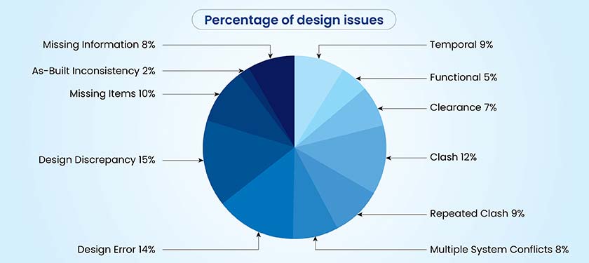
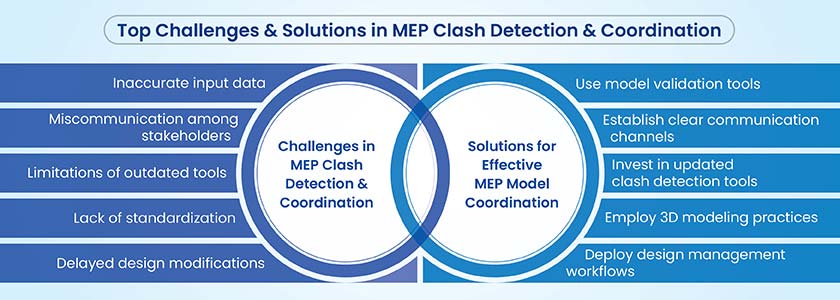
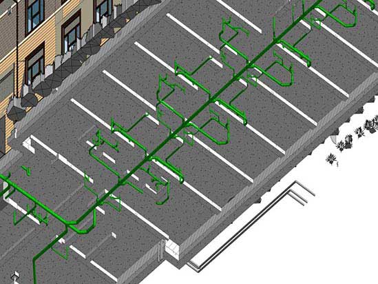
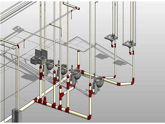
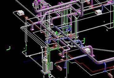
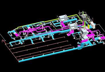
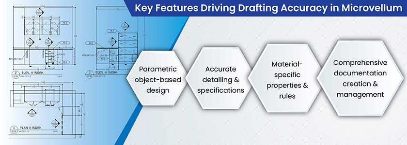
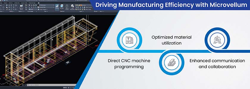
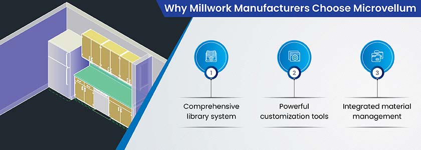
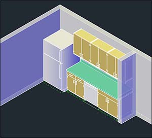
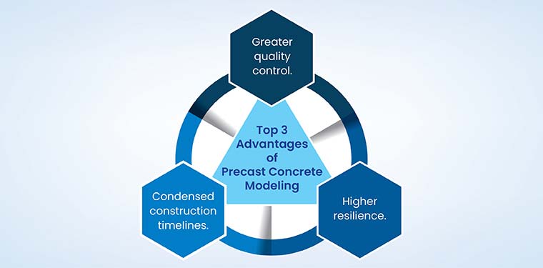
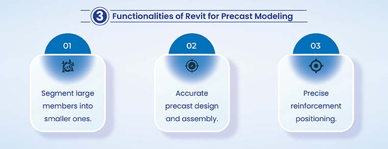
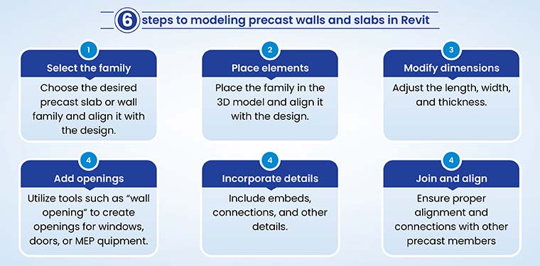
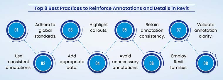

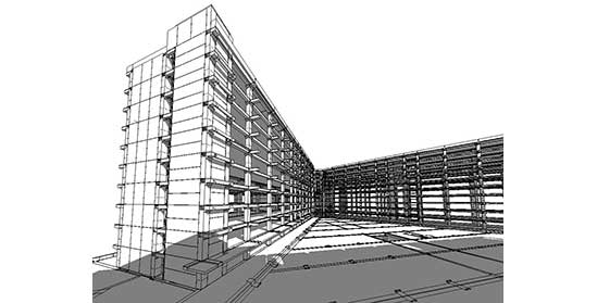
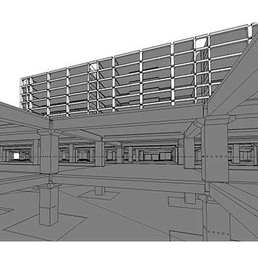
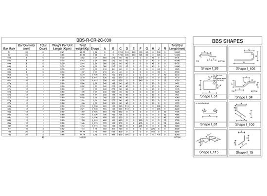
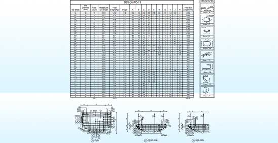
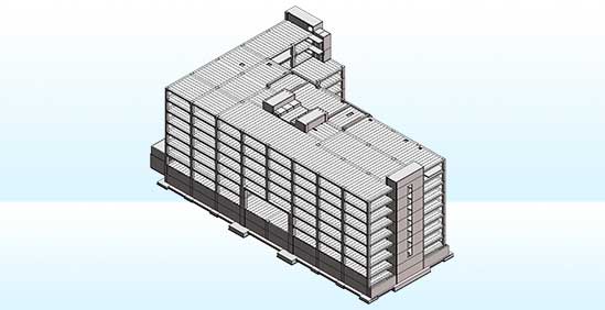
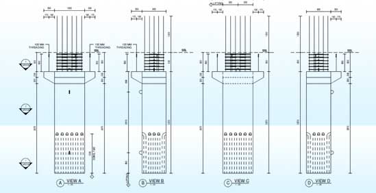
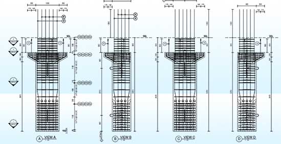
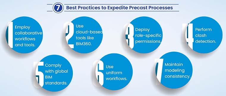
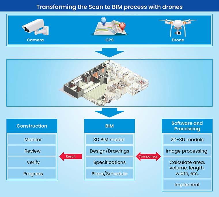
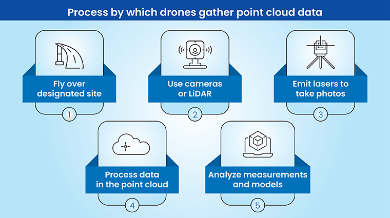

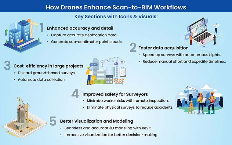
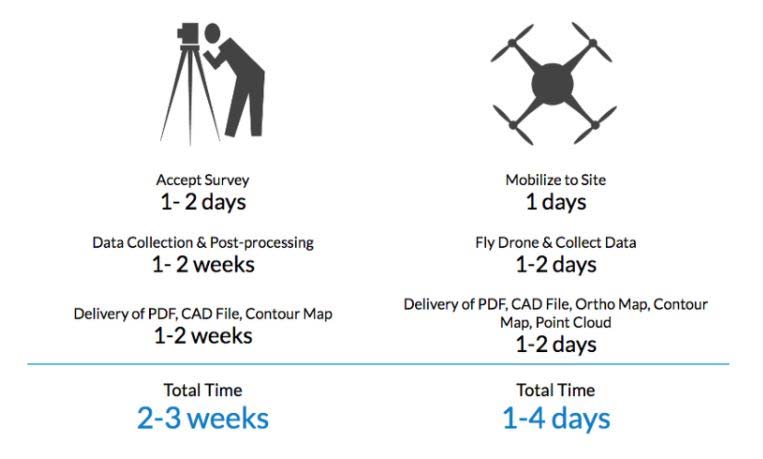
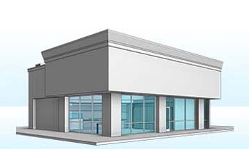

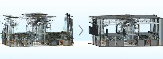
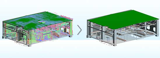
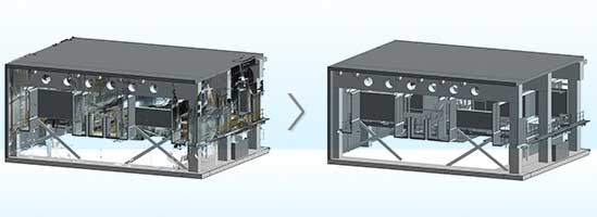
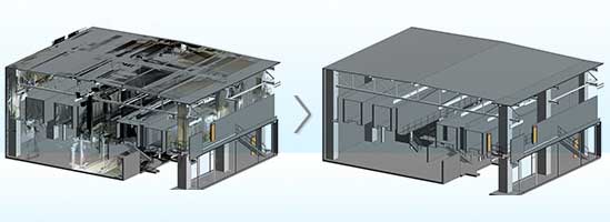
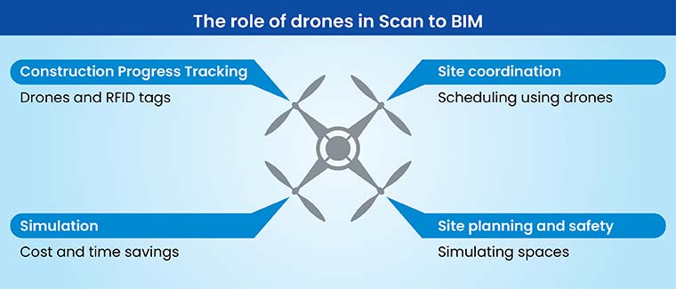
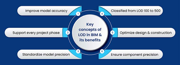
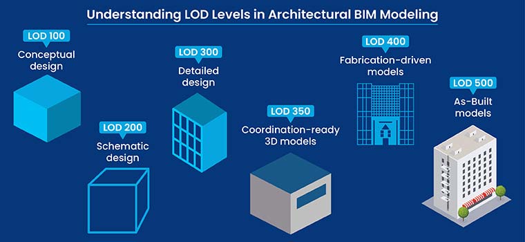

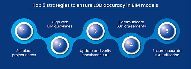
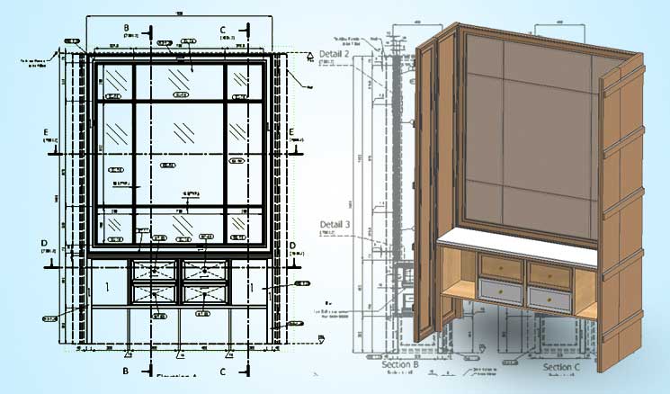
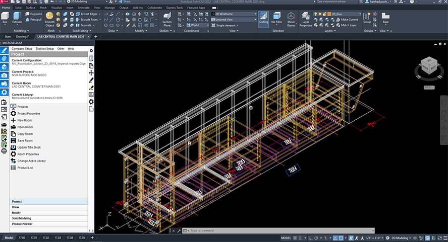
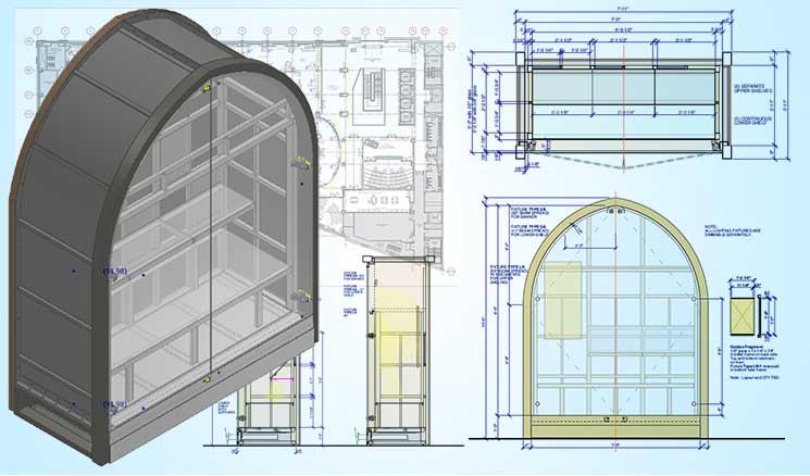
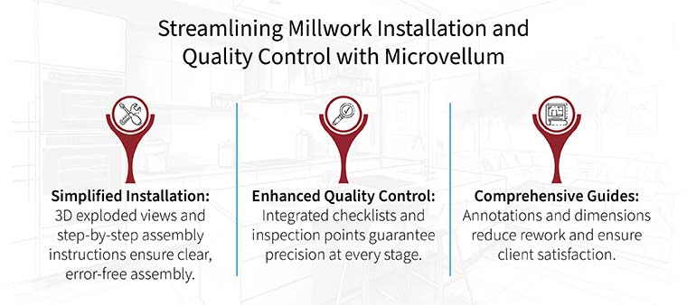
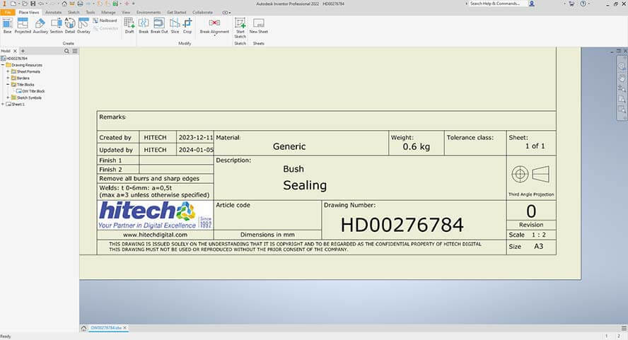
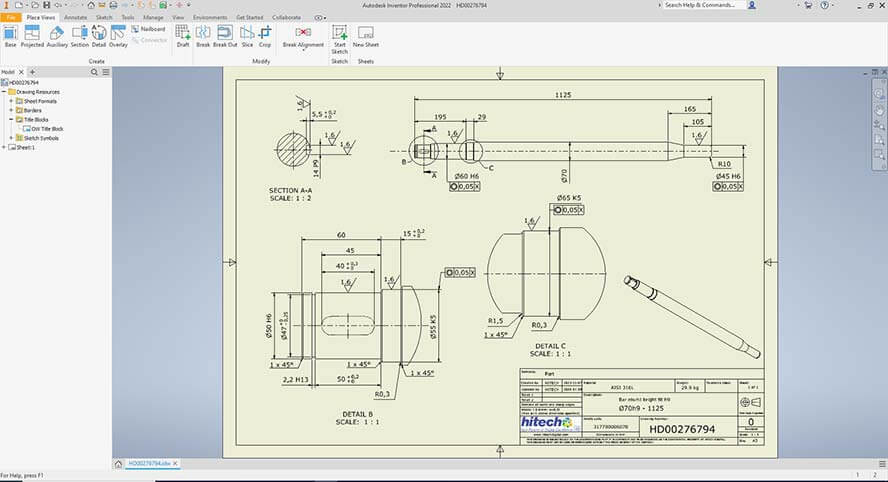
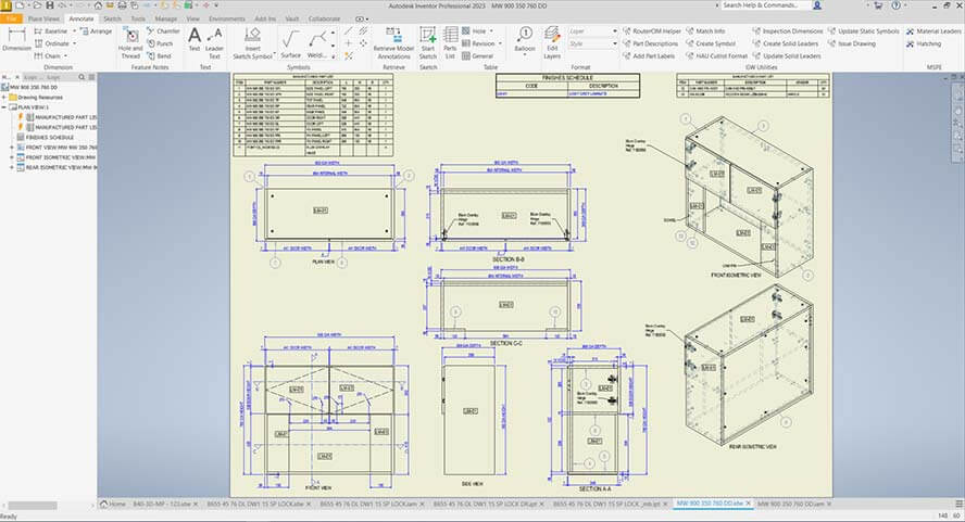
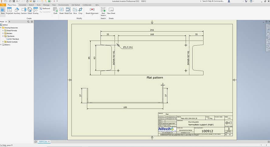
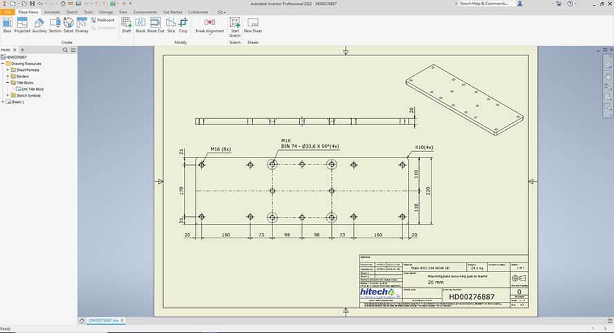
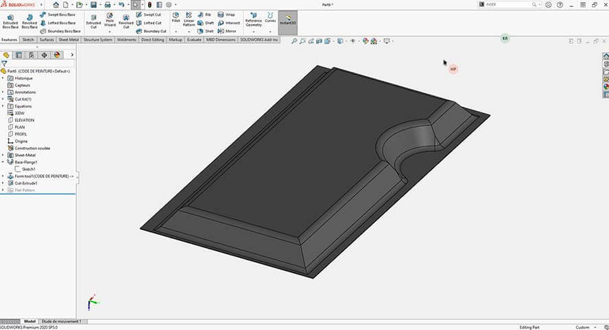
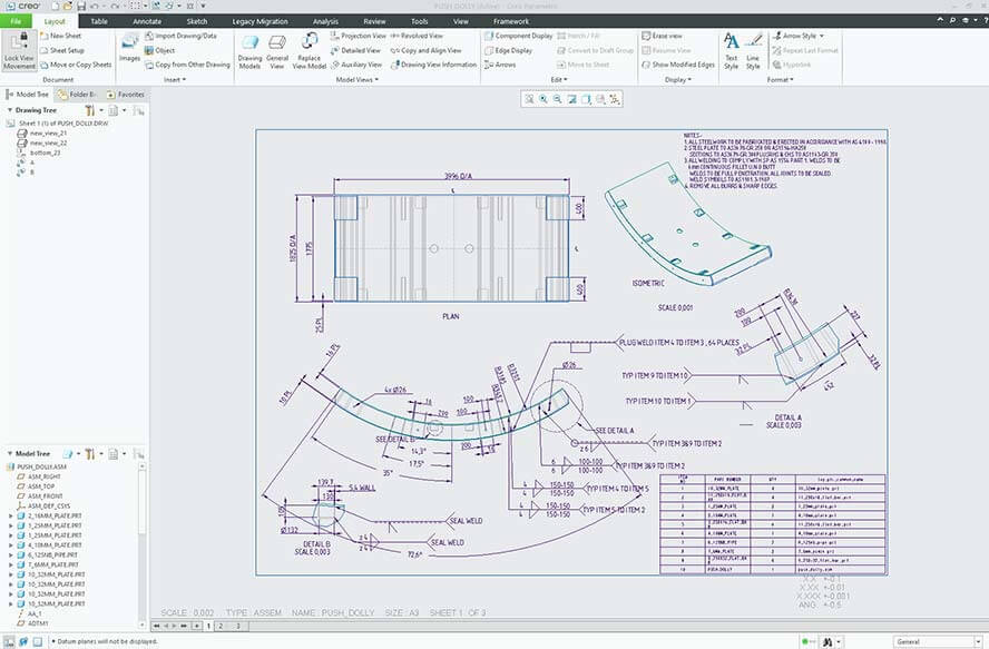
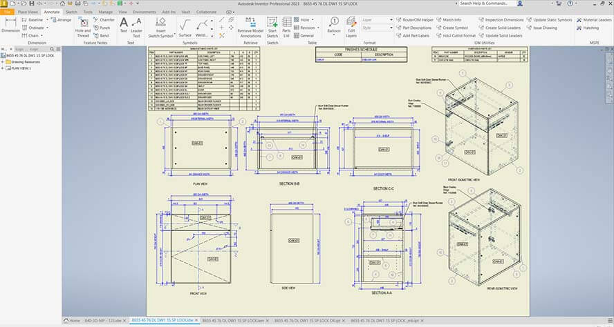
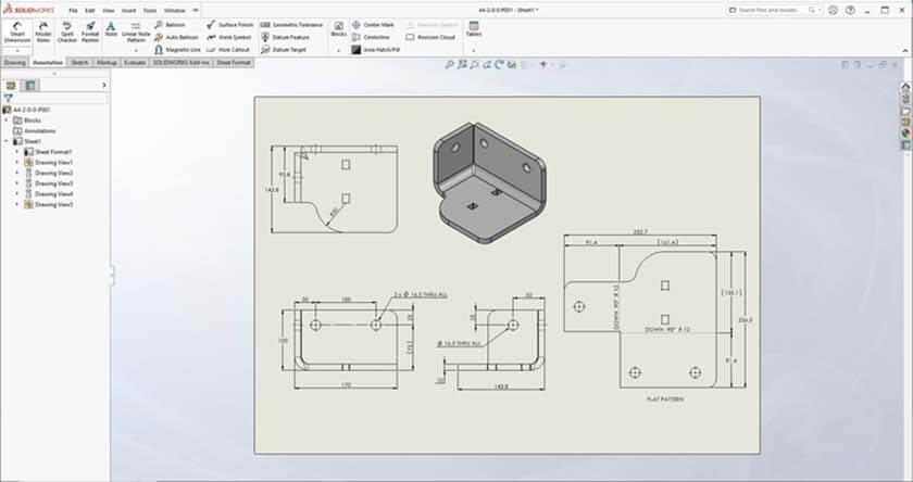
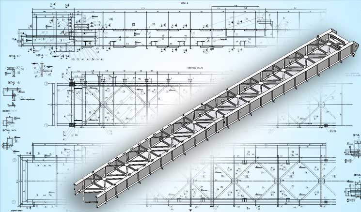
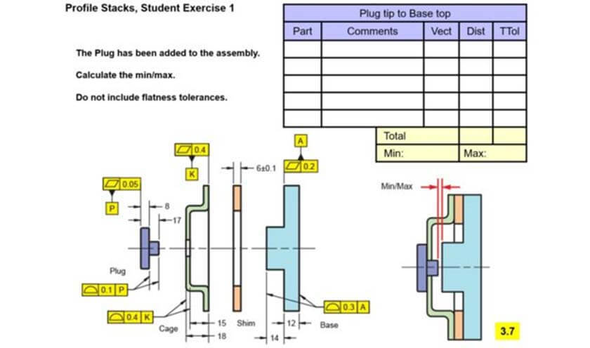

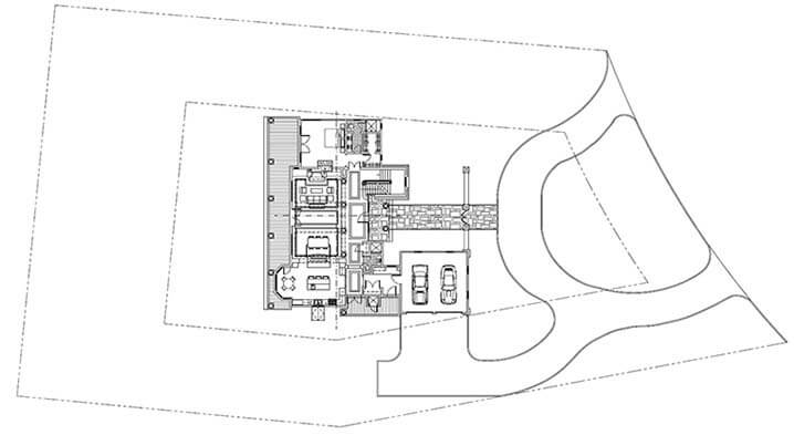
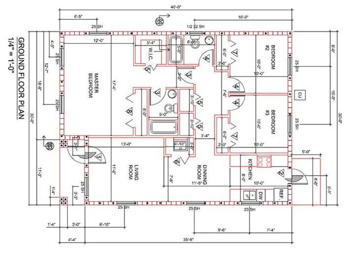
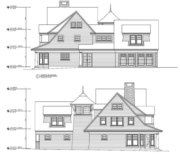
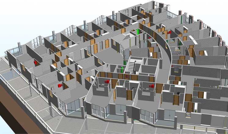
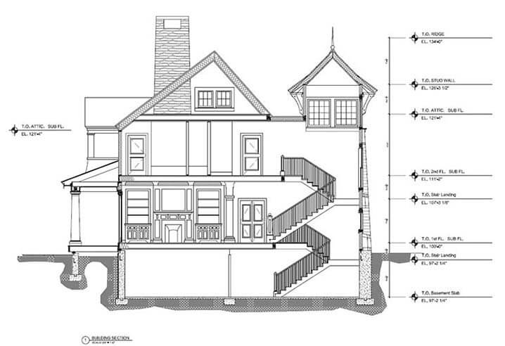
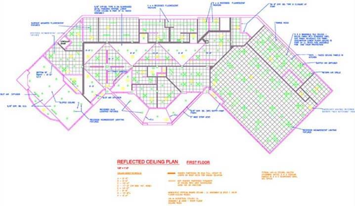
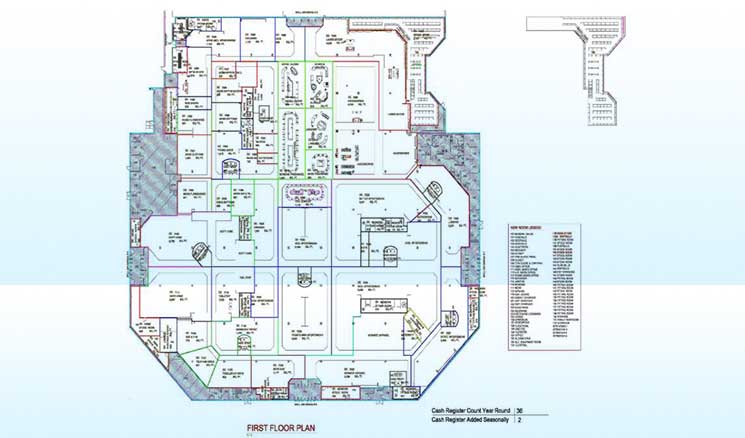
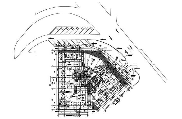
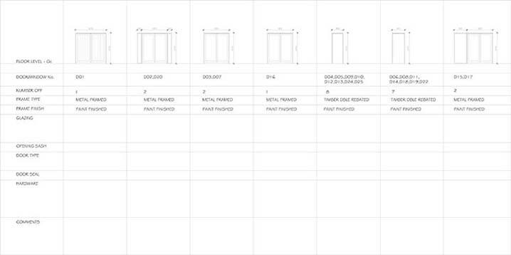
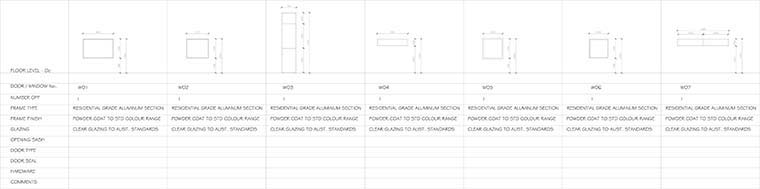
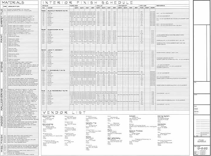
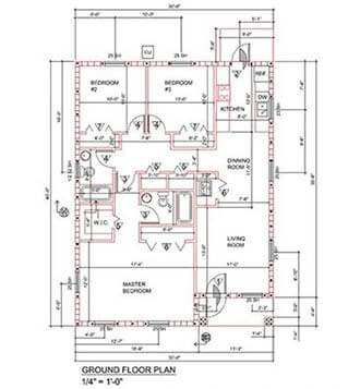
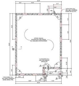
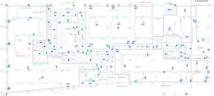
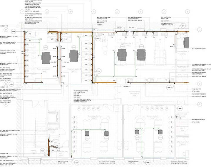
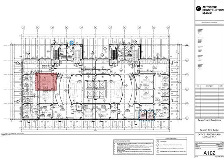
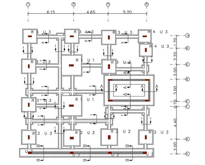
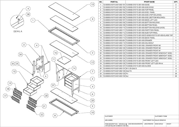
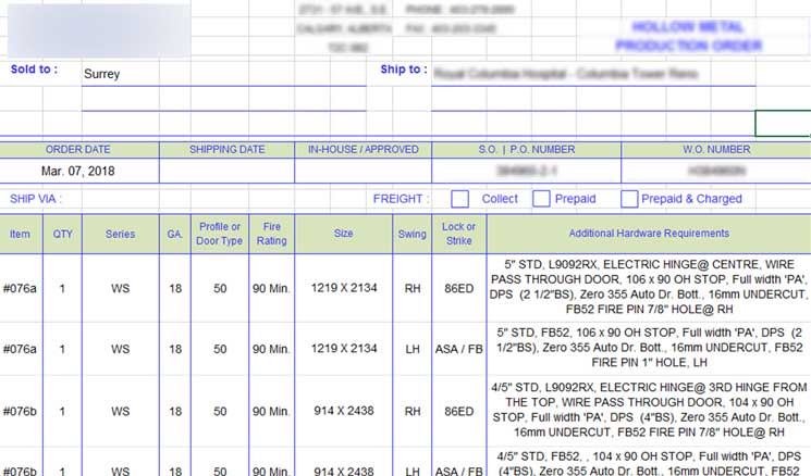


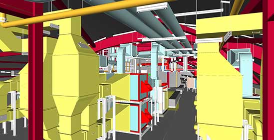
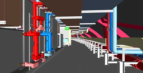

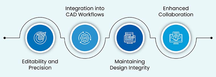
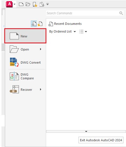
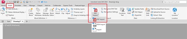
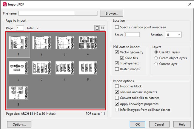
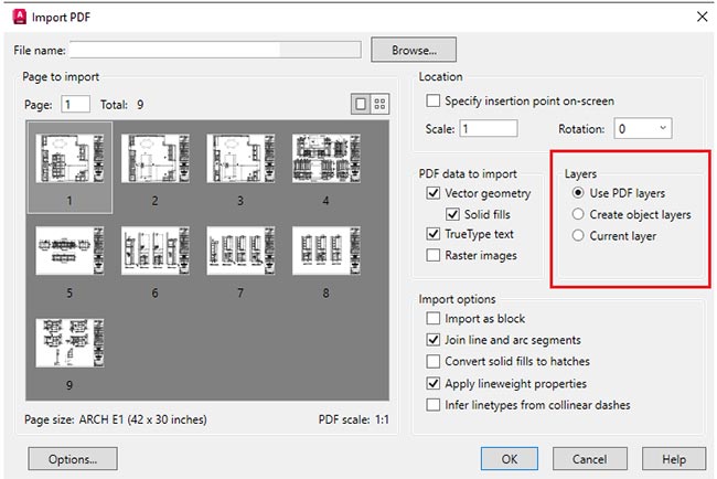
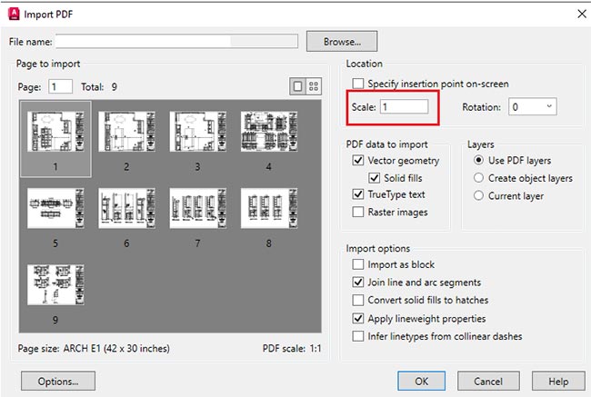
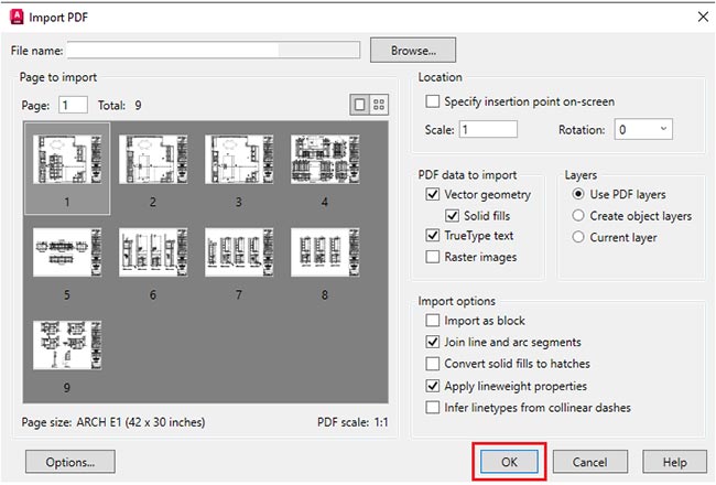
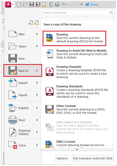
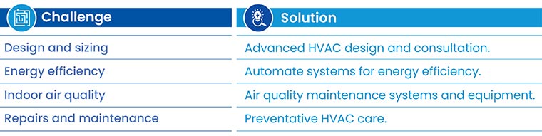
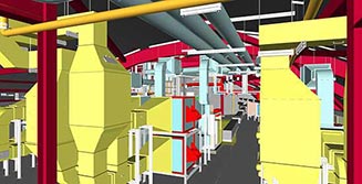

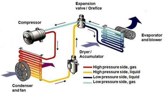

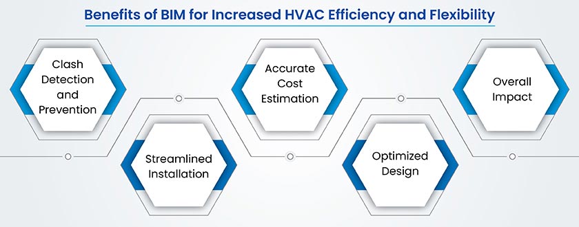
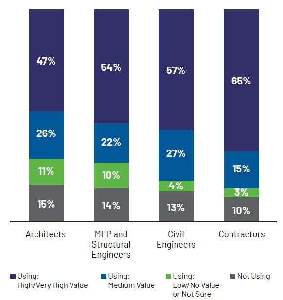


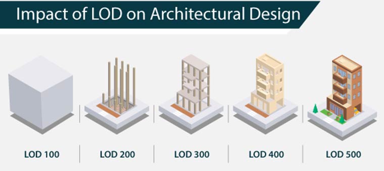
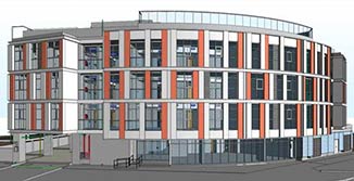
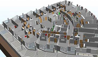
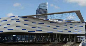
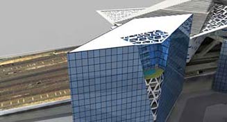
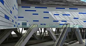
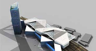
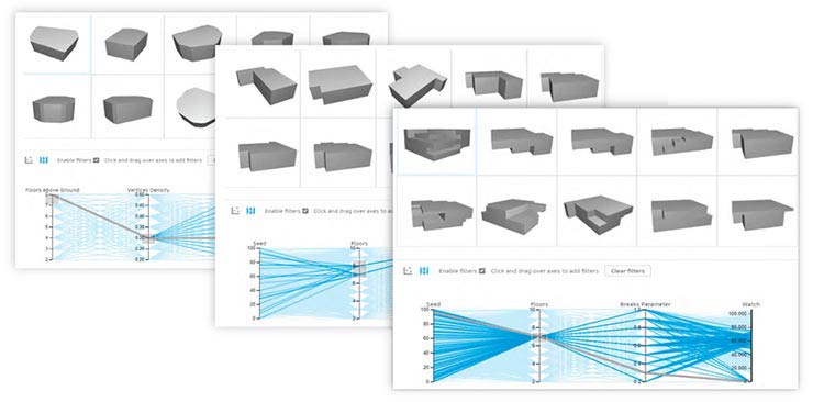


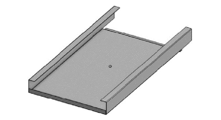
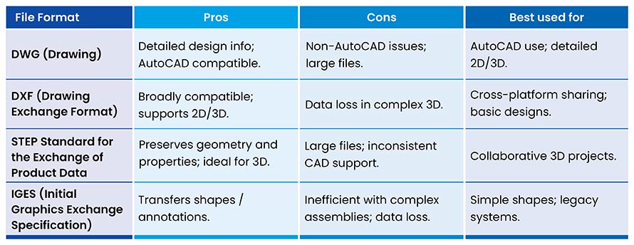


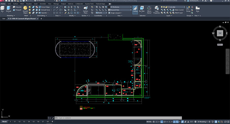
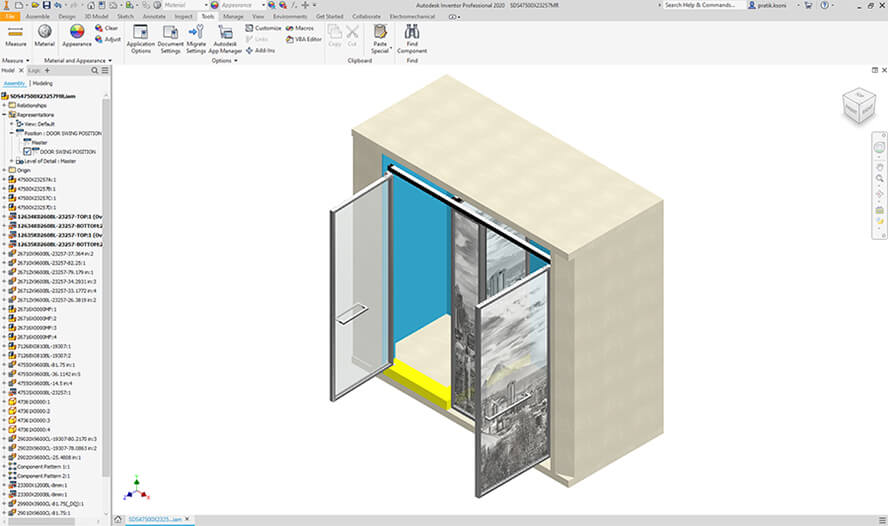
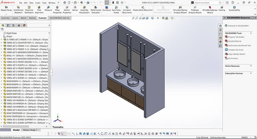
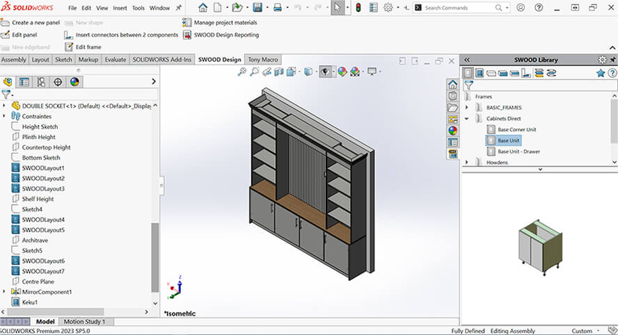
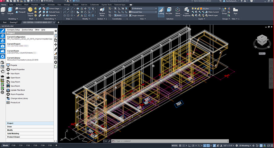
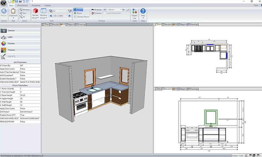
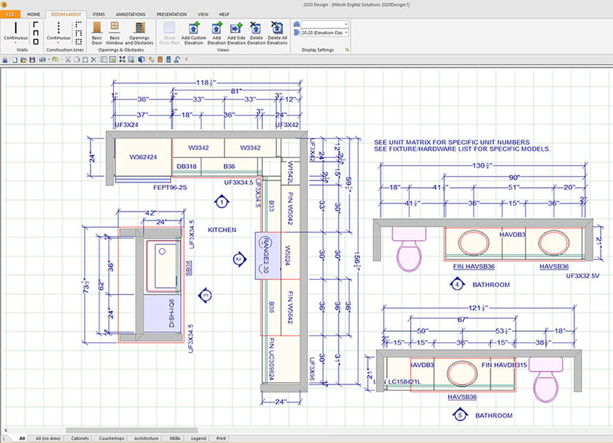
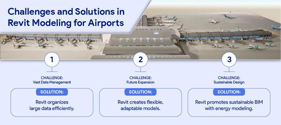

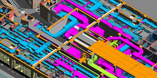
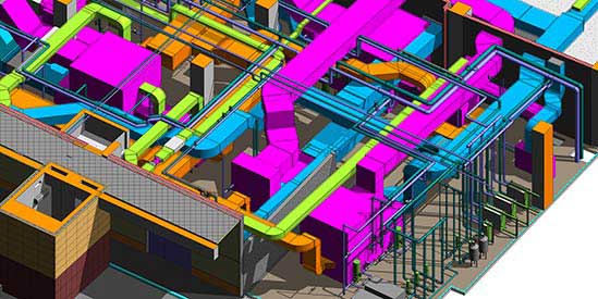
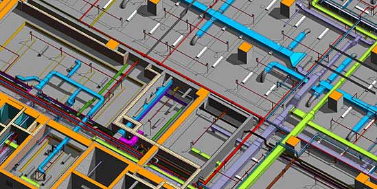

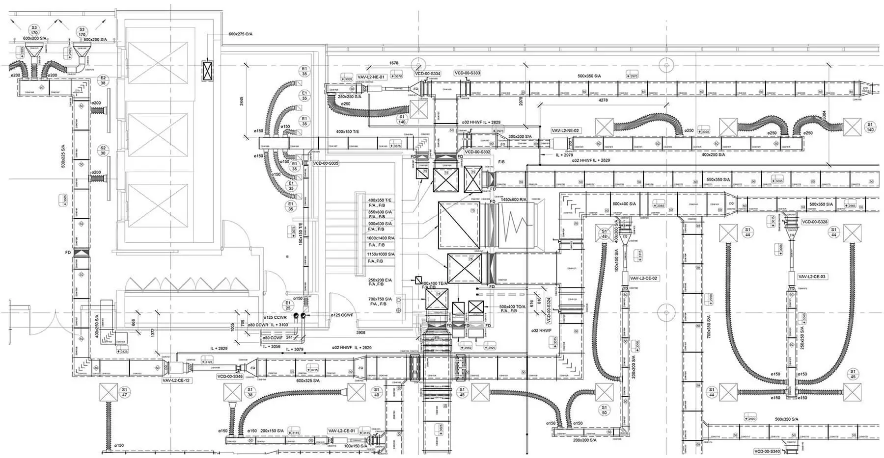
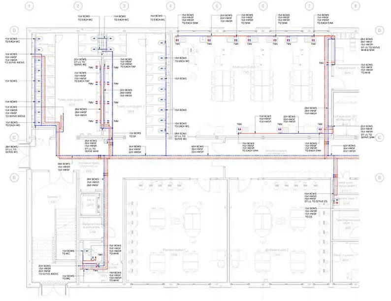
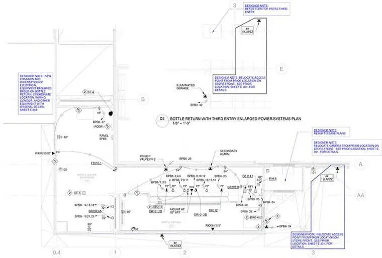
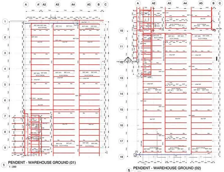
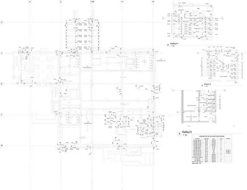
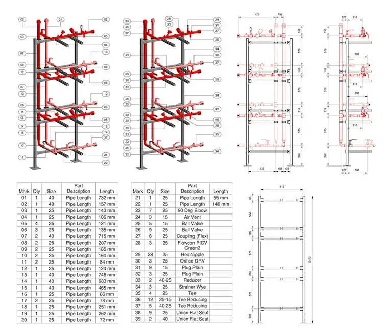
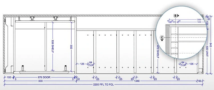
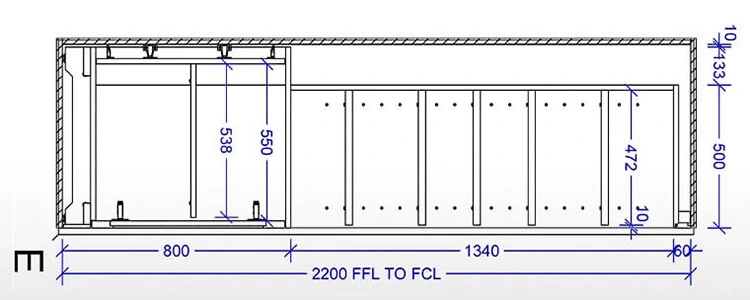
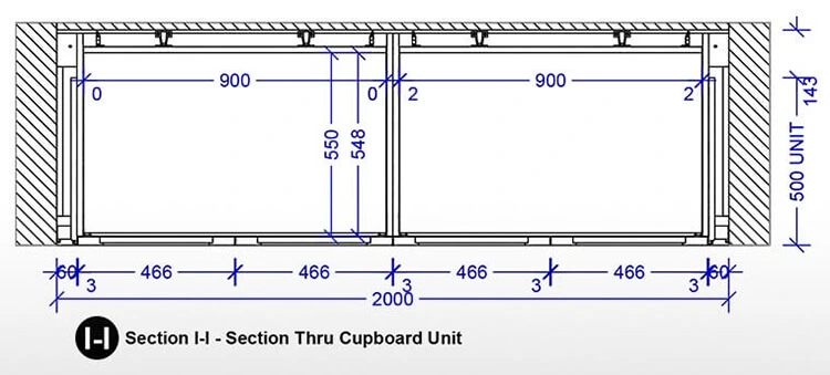
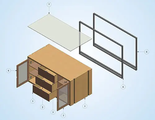
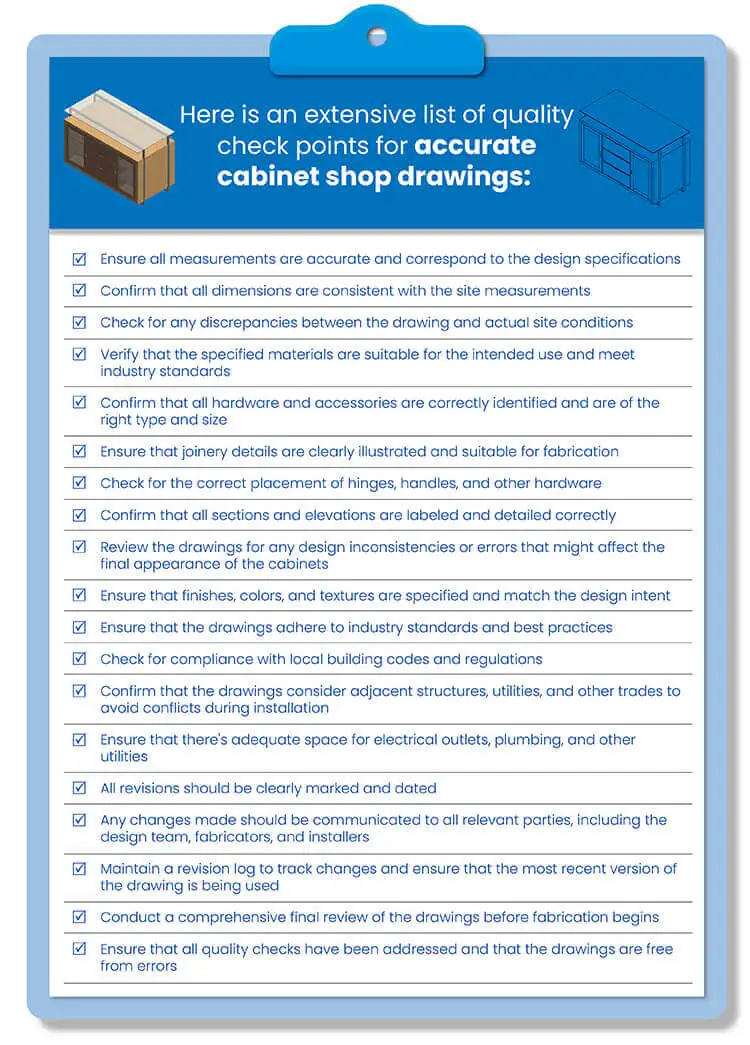
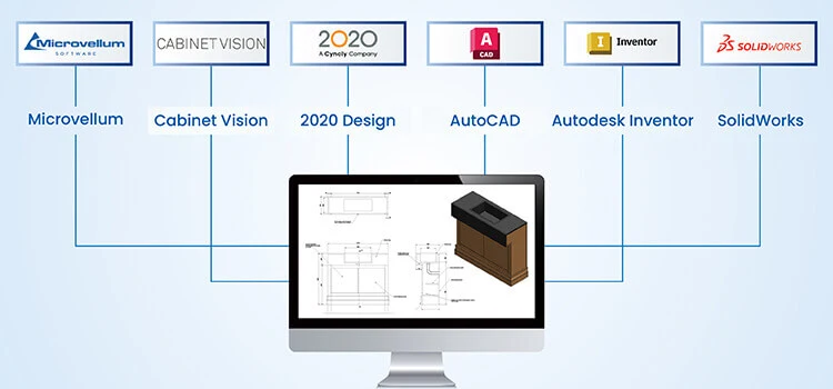


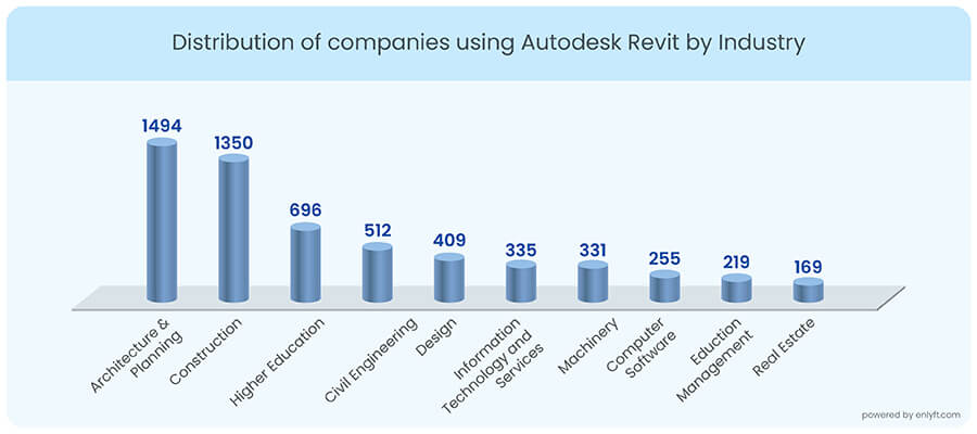
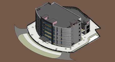
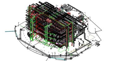
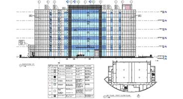

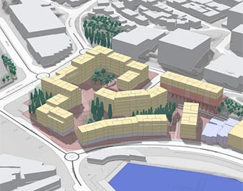
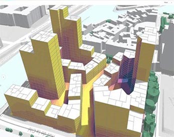
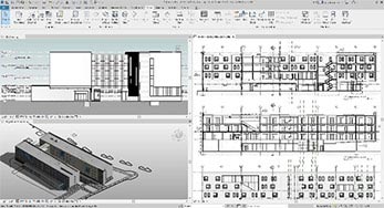
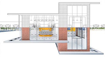
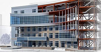
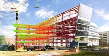
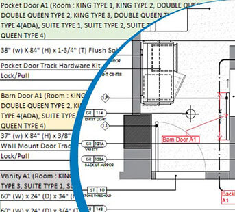
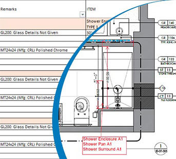
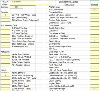
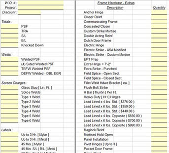
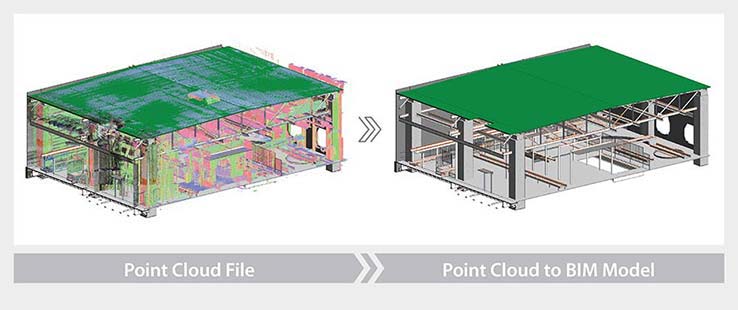


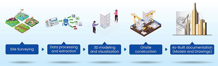
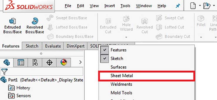
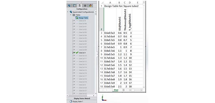
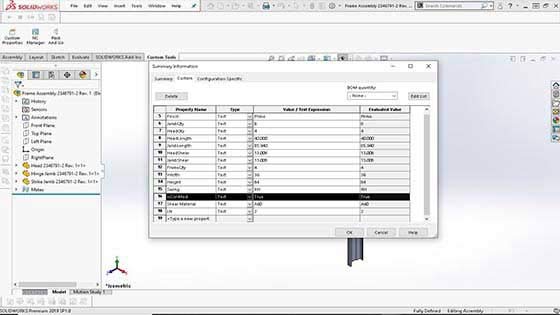
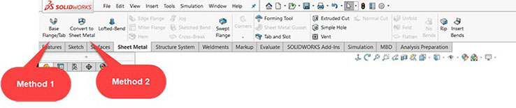
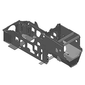
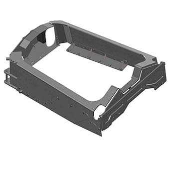


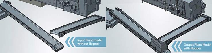
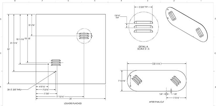
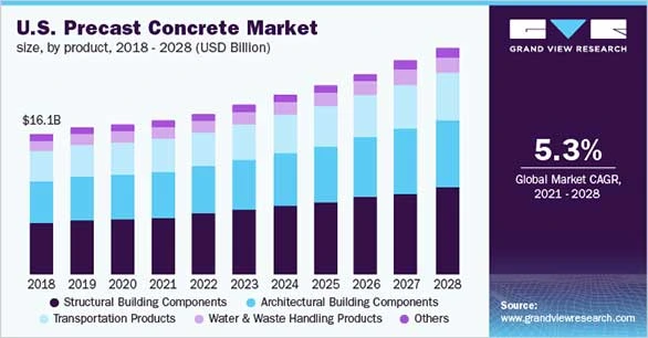
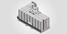
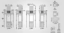
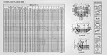
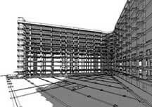
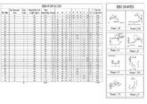
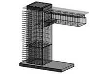
 Read more here
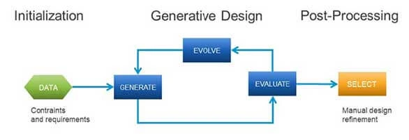
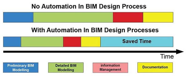
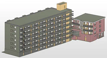
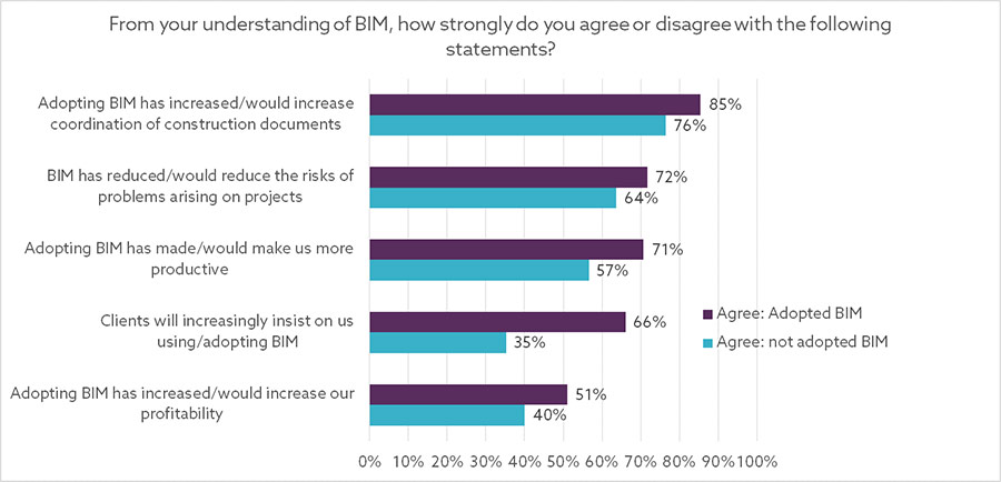
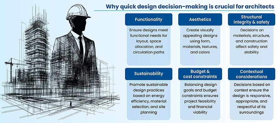
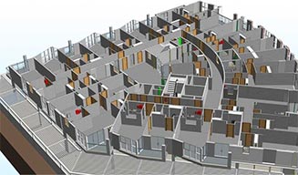
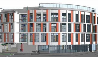
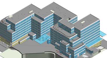
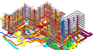
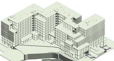
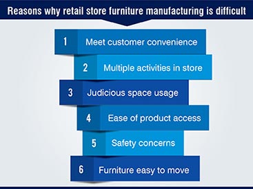
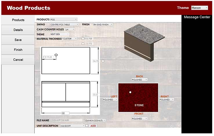
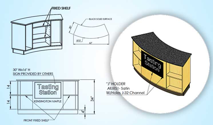
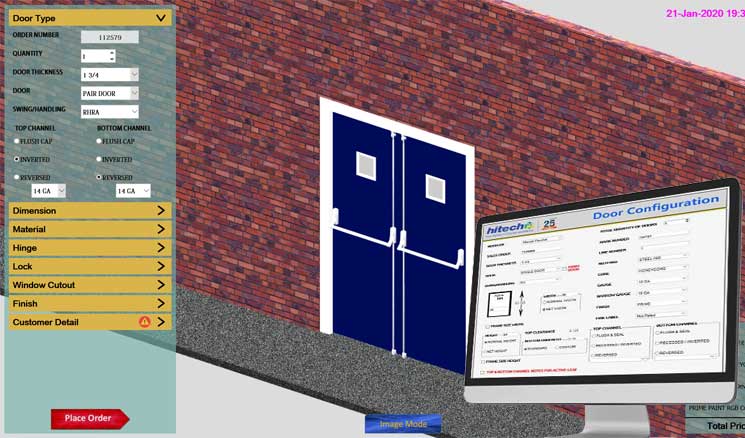
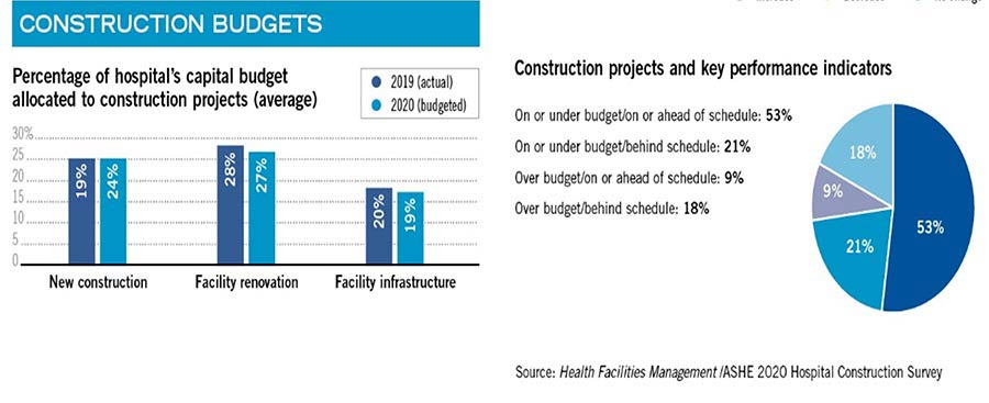
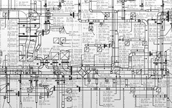


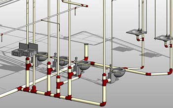
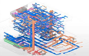
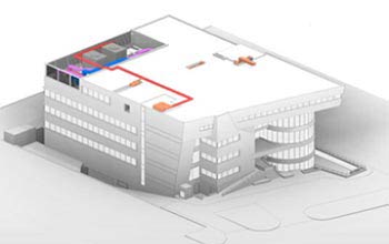
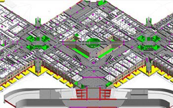
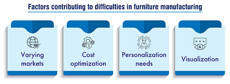

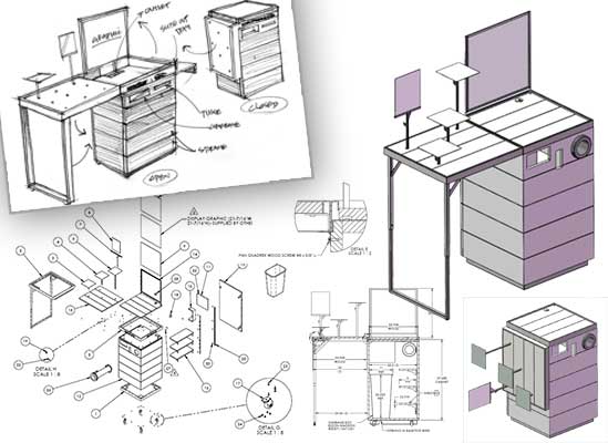
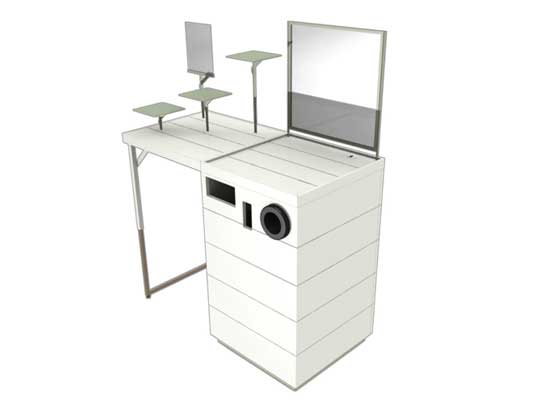
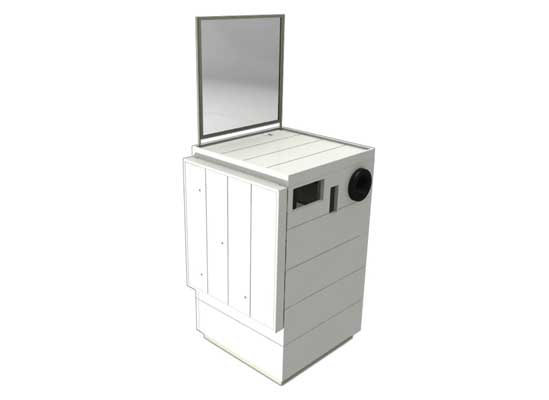
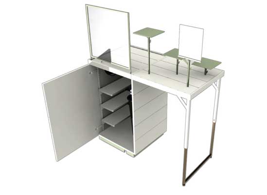

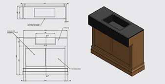
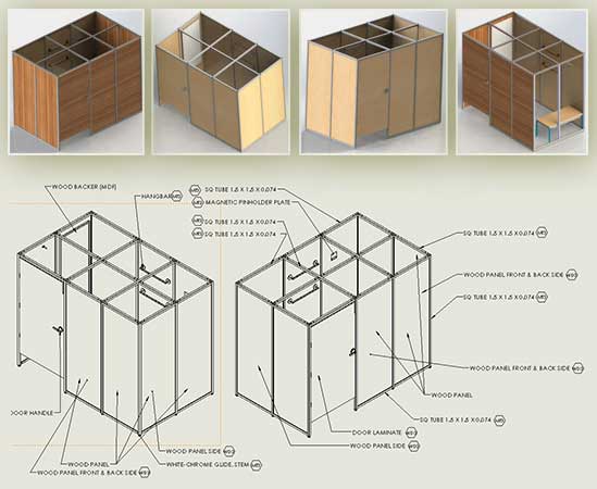
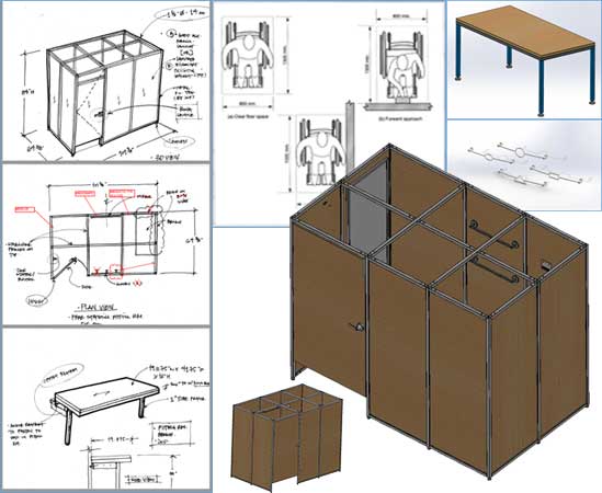
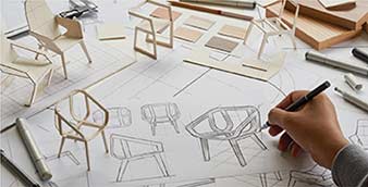
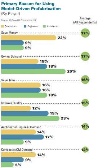
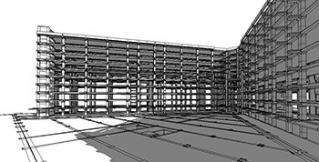

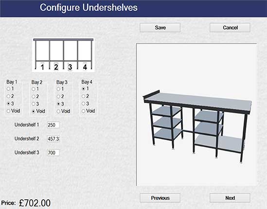
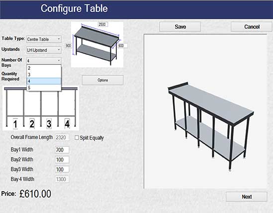
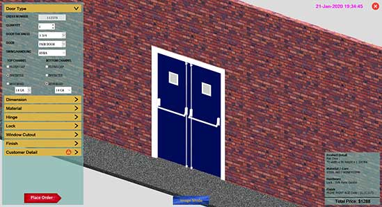

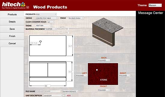
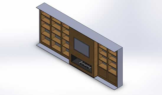
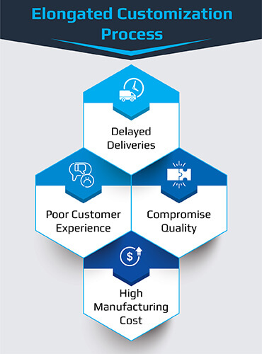
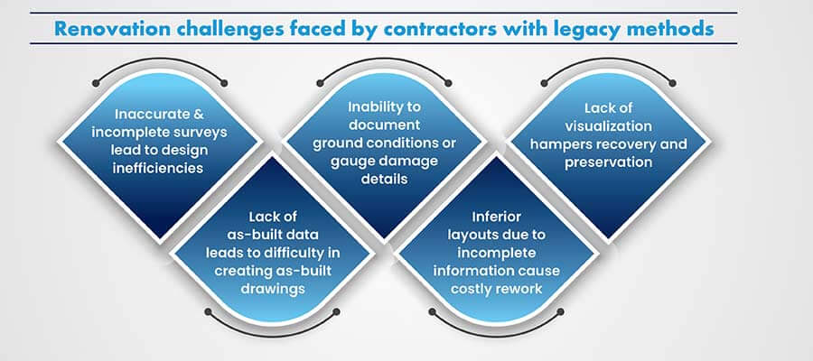
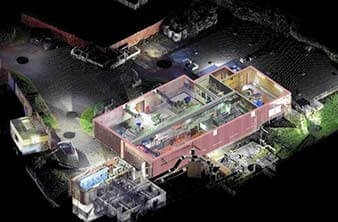
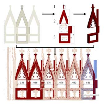
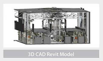

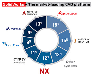
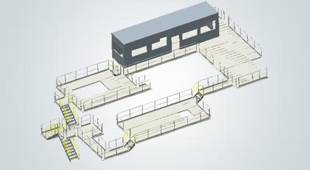
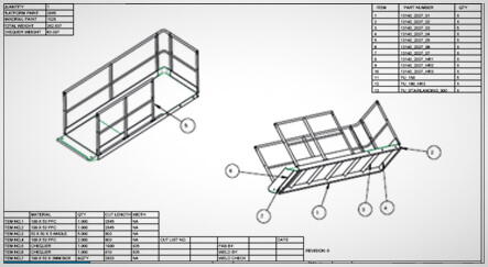
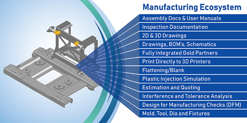
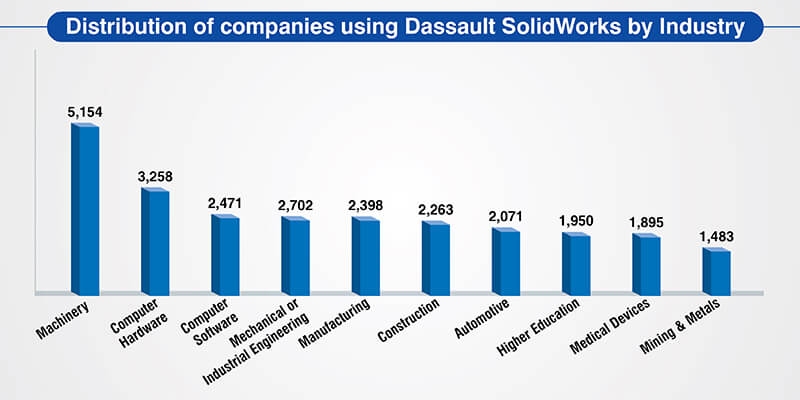
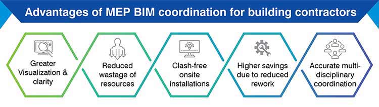
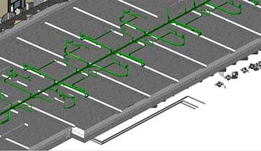
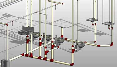
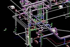
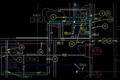
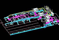
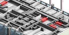
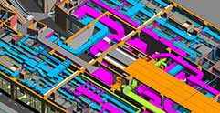
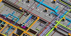
 Partner with us for your BIM modeling needs →
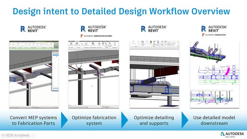

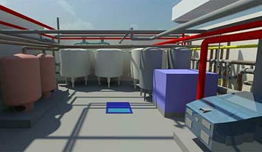
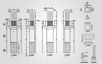


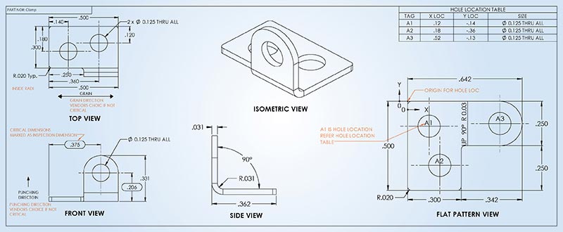
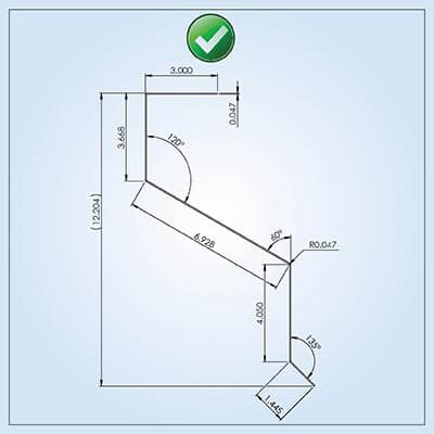
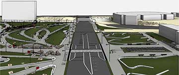
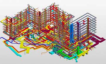
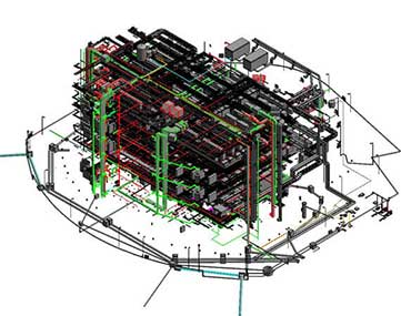
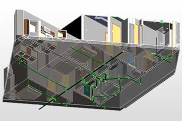
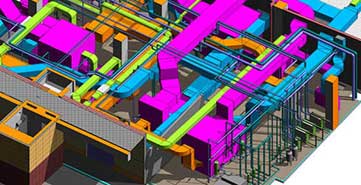
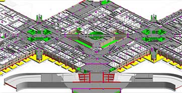

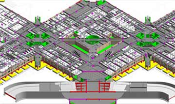
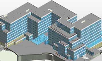
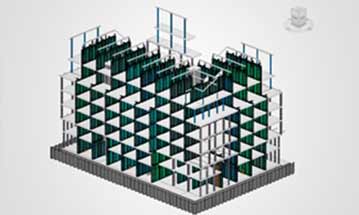
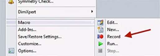
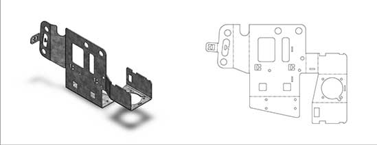
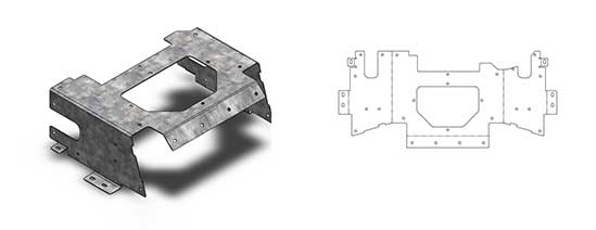
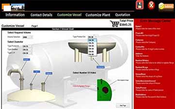
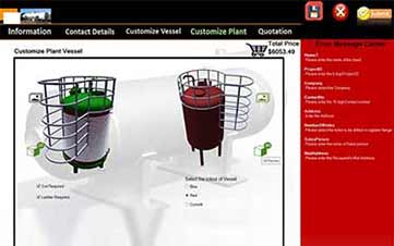
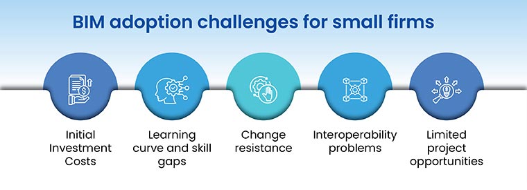
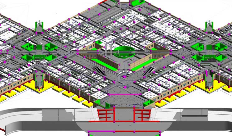
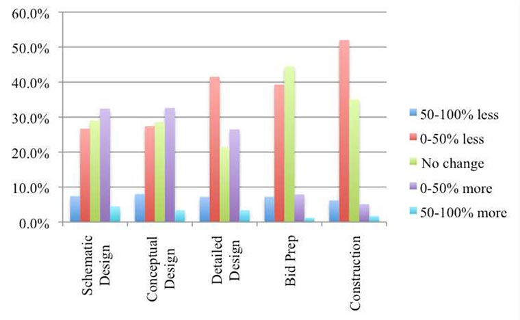
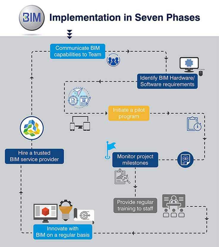
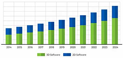
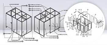
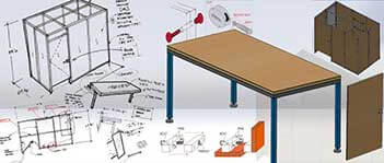
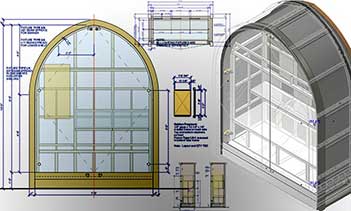
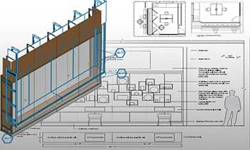
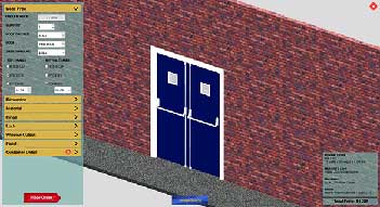
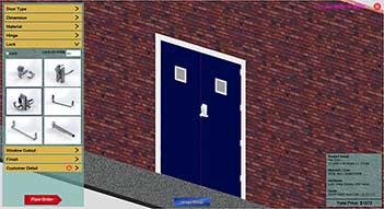
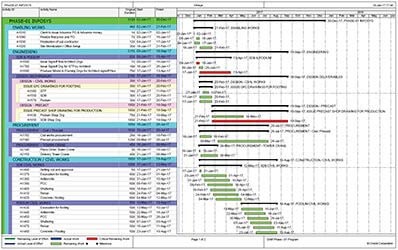
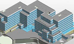
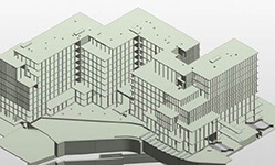
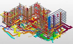
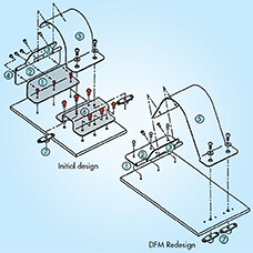
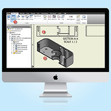
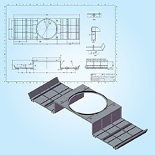
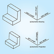
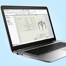
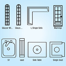

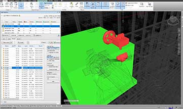
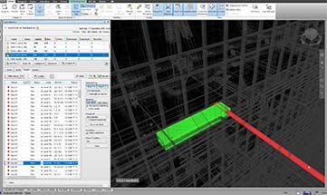

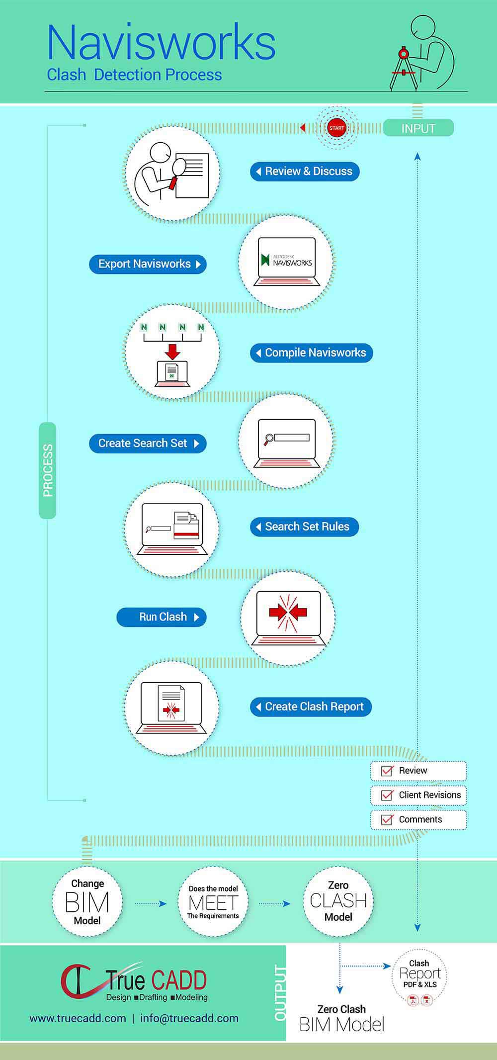

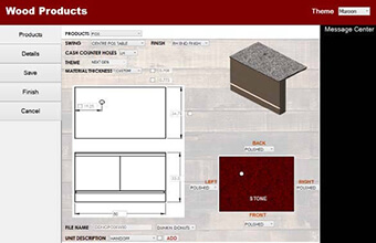
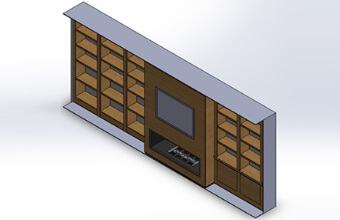

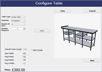
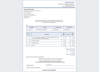


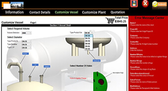

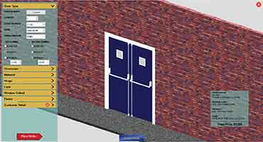
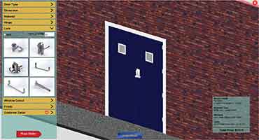
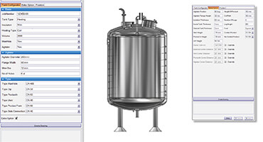
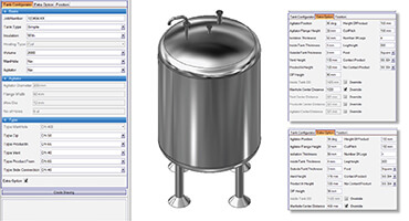
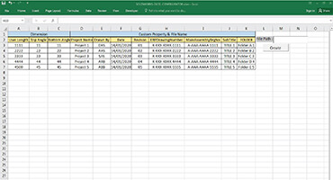
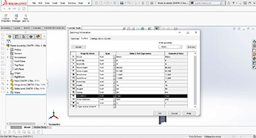


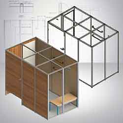

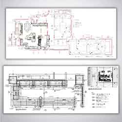

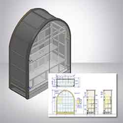


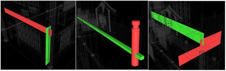
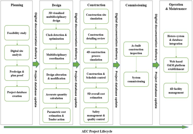
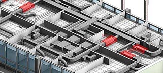
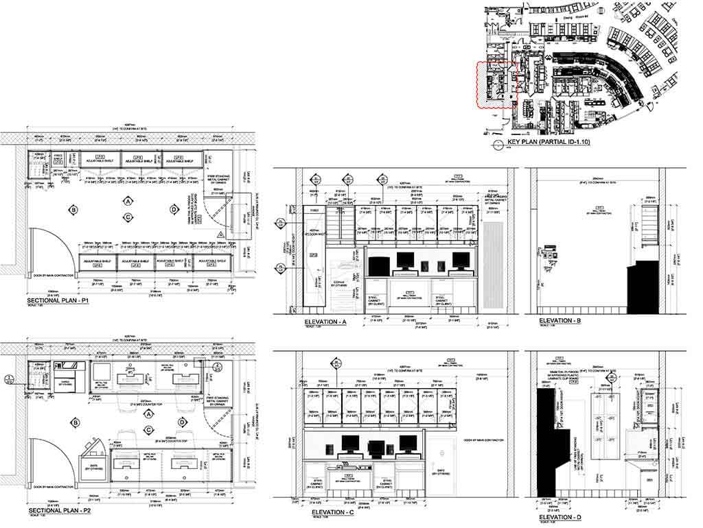

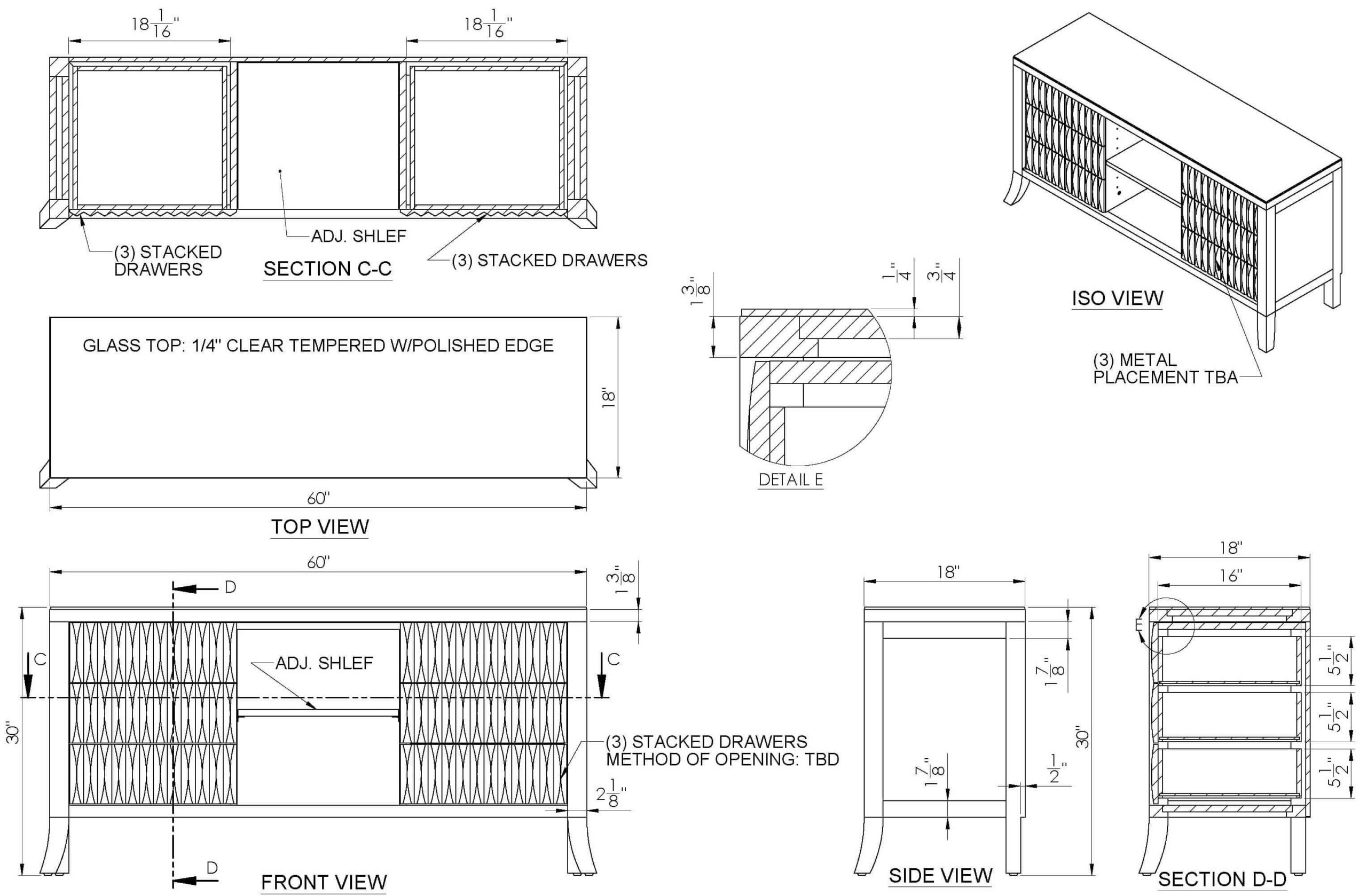
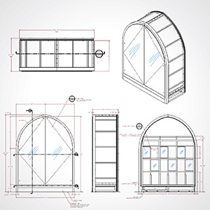
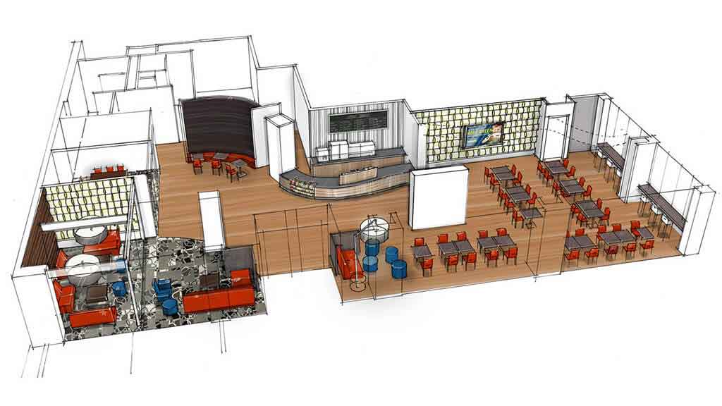
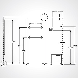
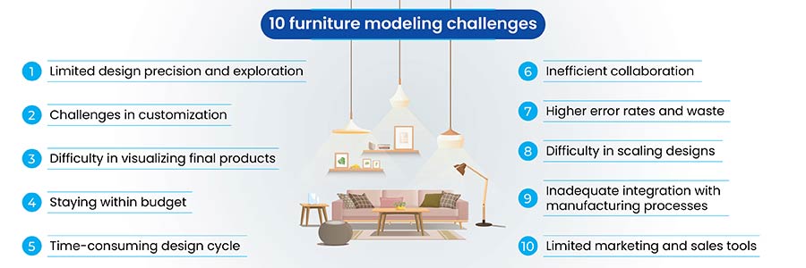
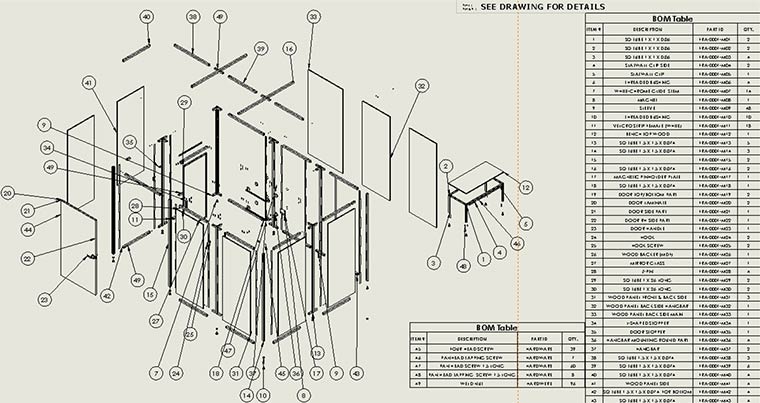
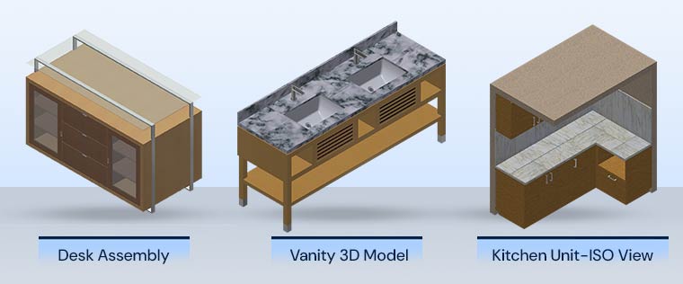
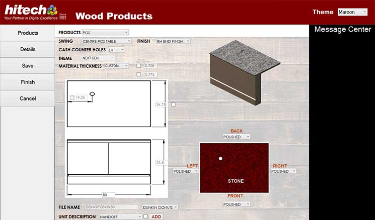
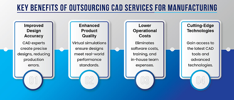

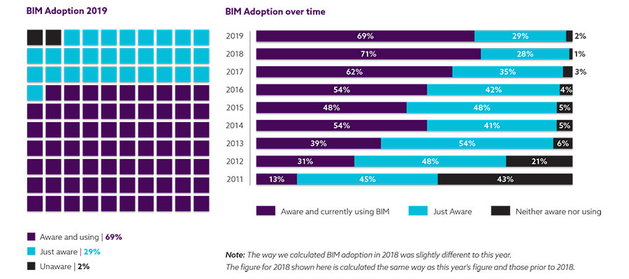

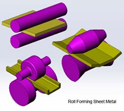
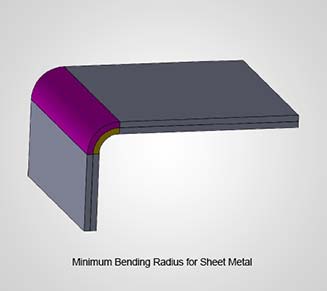
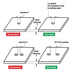
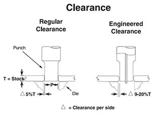
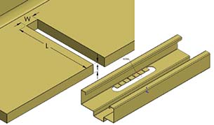
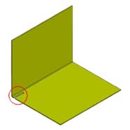
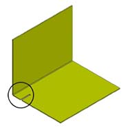
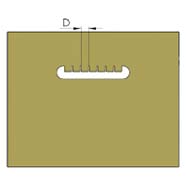
 Accuracy & Speed
 Price Optimization
 3D Visualizations
 Real-time Visibility
 Upselling & Cross Selling
 Multi-platform Support
 Reporting
 Guided Selling


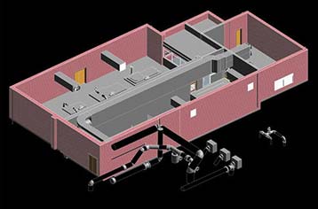
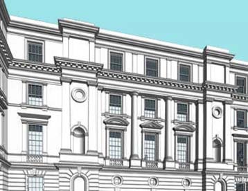
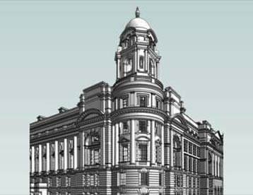
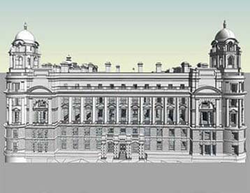
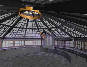
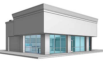
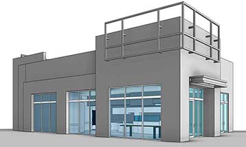
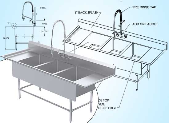
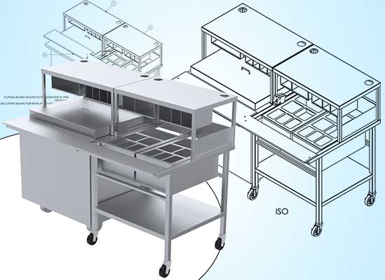
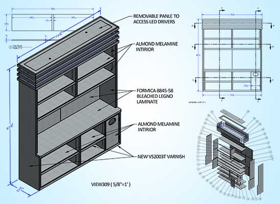
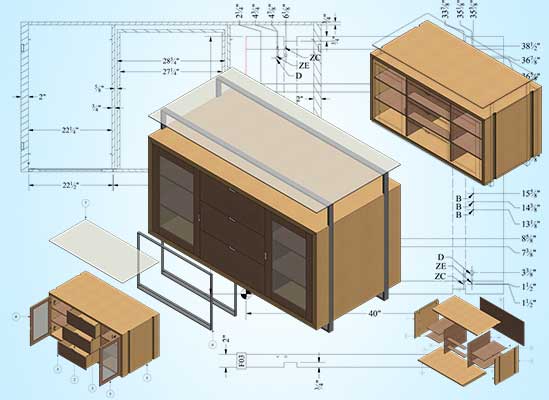
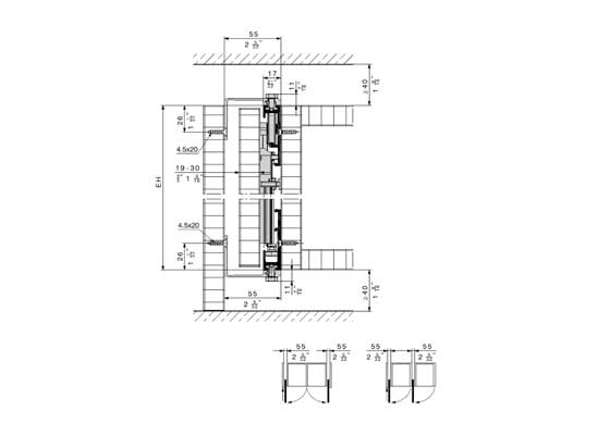
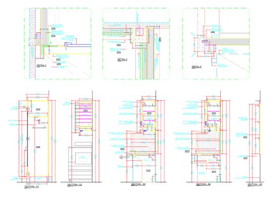
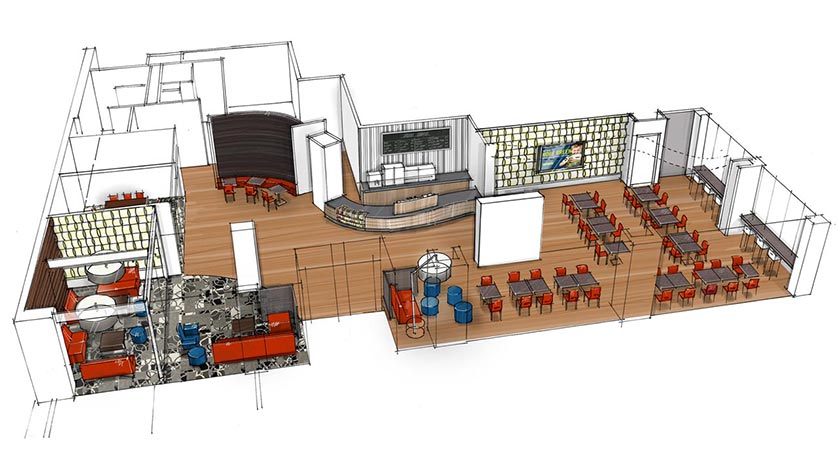
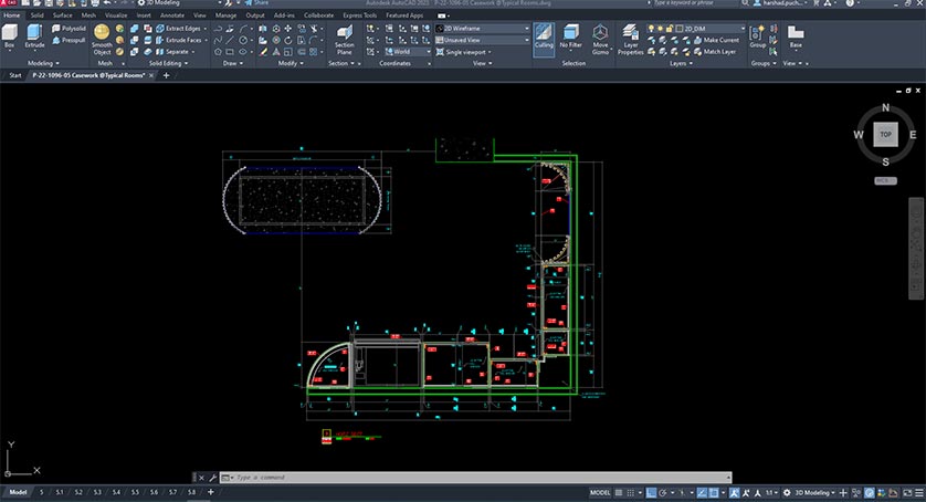
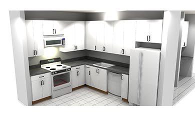
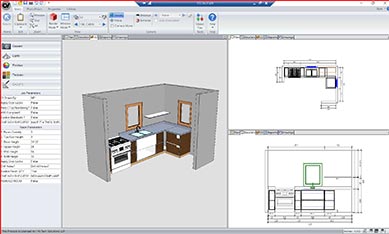
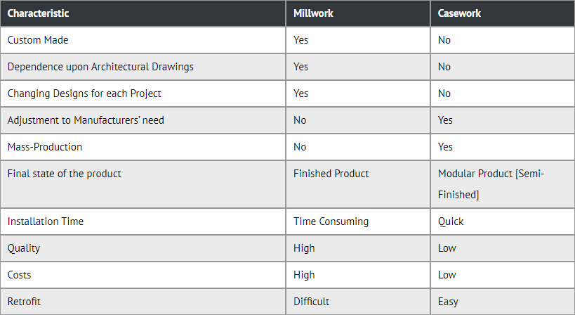
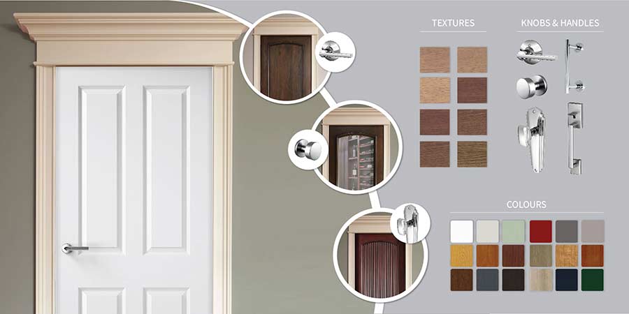
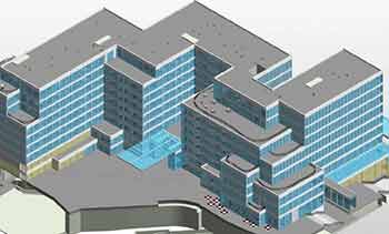


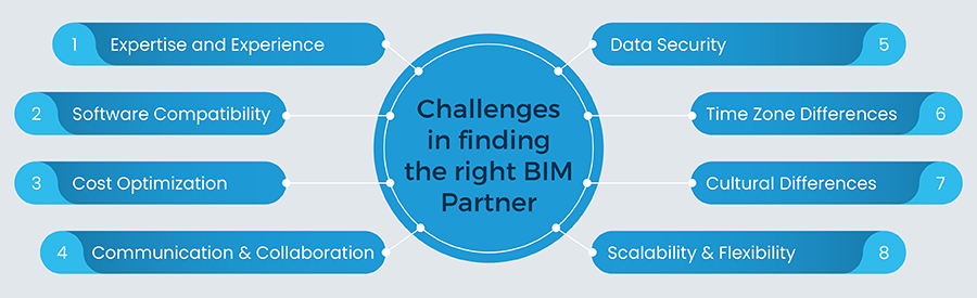
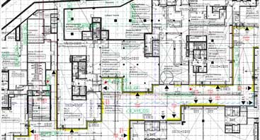
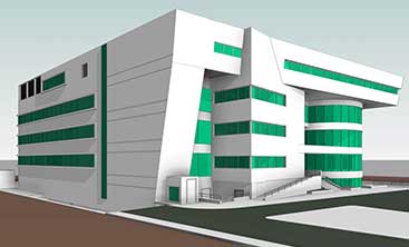
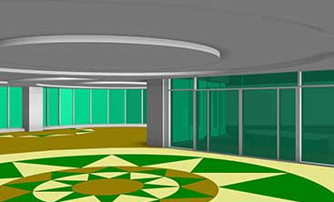
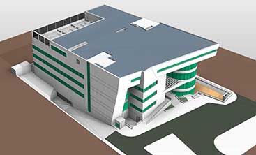
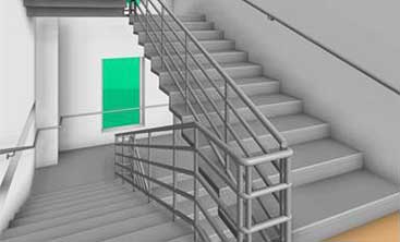

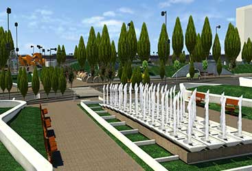
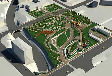
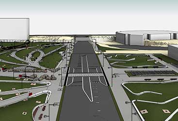
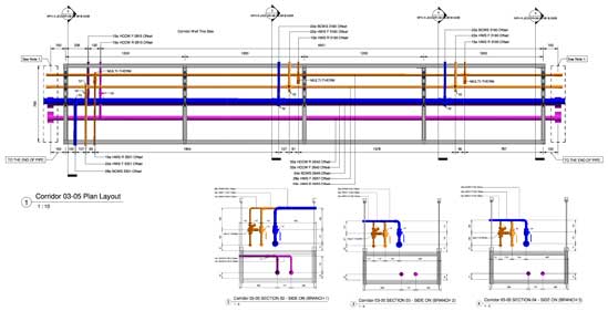
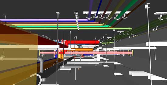
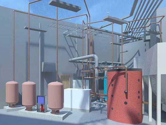
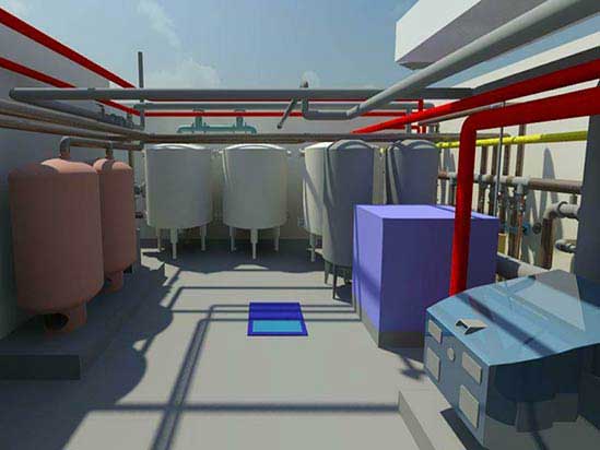
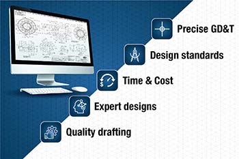
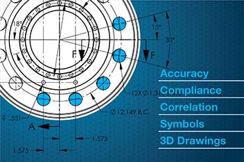

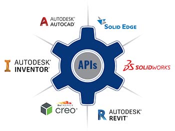


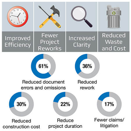
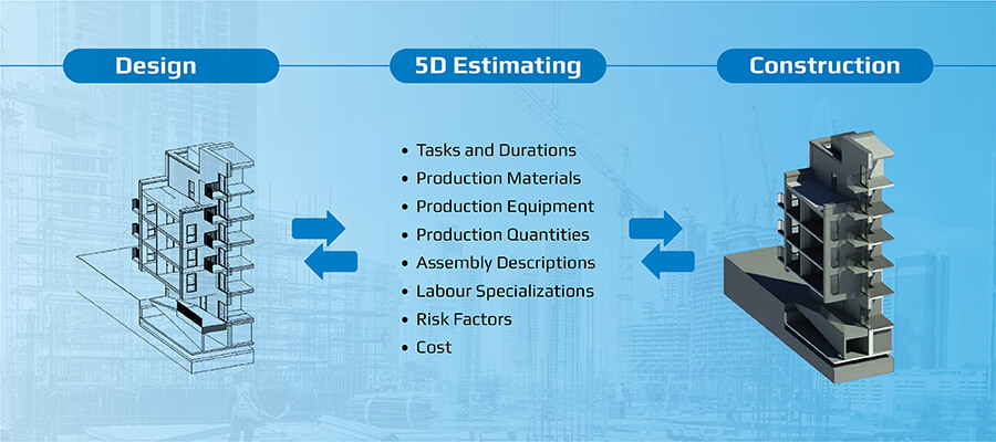
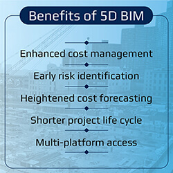


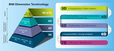


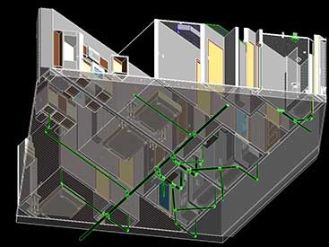
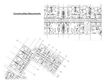
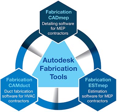


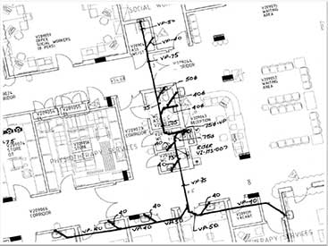
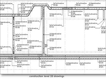
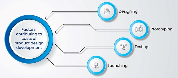

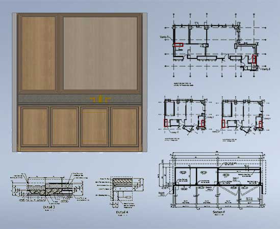
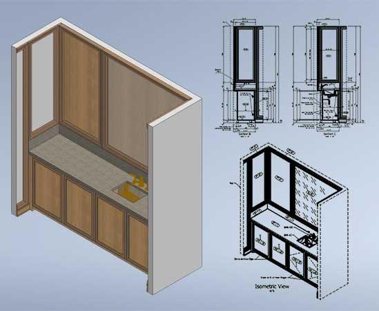
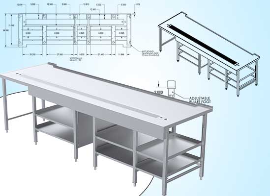
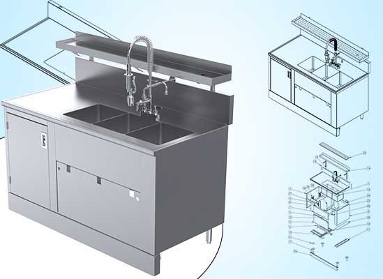
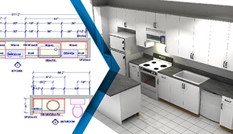
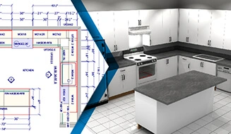
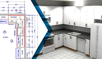
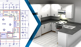
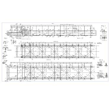
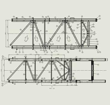
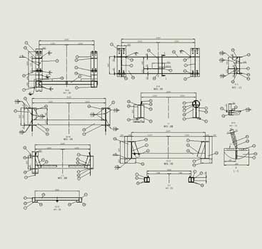

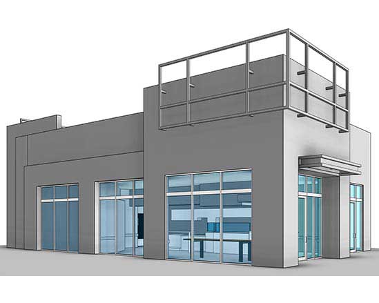
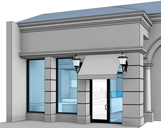
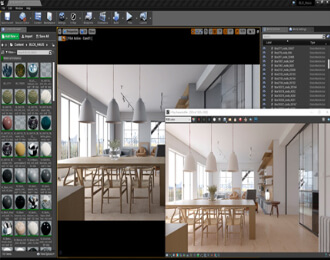
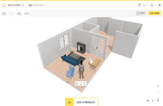
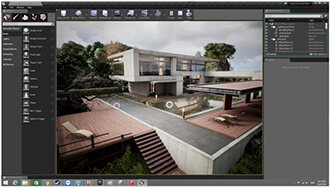
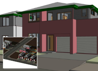
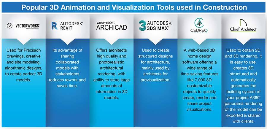
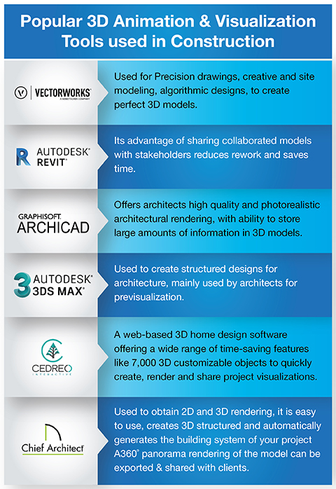
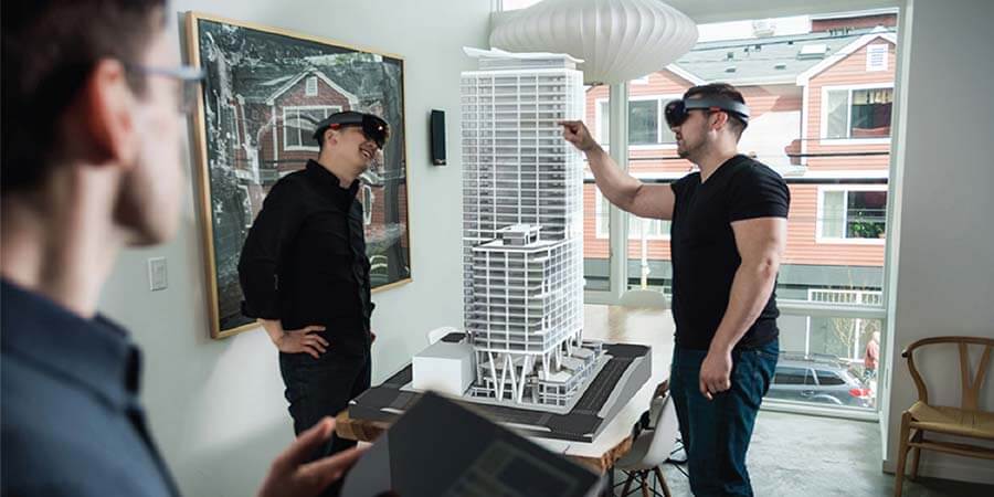
For example, it is assumed that the X mm diameter of the hole can be punched using a tool of X mm. While in reality, the diameter is X+n mm, where n is the clearance between the tool and metal sheet for heat dissipation through air.